Logo

V/P 350 Late 80s Cooling System Issue

jon_allen

Regular Contributor
Hi Gang

I have a tough one here. I know I have come to the right place.

Engine is a reman 350 Gm. The block is cooled with anti freeze and the exhaust with seawater.

It has new exhaust manifolds and elbows, a new 140f thermostat (I know it should be a 160f)

It has a new Johnson FS-6 crank mounted seawater pump. This is the lager model for use with a heat exchanger.

The heat exchanger was just serviced.
 
Hi Mark

The post got cut off some how, my apologies. My problem is that I installed an engine overheat alarm switch which triggers at 200 degrees to the left of the thermostat housing as viewed from the front of the motor.

The motor runs at 140 Degrees at idle. While idling the temp switch is activating the alarm. Measuring the body of the temp switch with an Infra red temp gun it reads 192 degrees when it triggers which is ok.

The problem is that the factory temp sensor body located 8 inches away in the same passage is reading a 138 degrees.
what I have here is a 55 degree temp difference over the span of the thermostat passage in the intake manifold.

I thought perhaps the rebuilder may have installed the intake or head gaskets incorrectly possibly blocking a cooling passage.
My machinist says it's not possible on a SBC.

Any help would be greatly appreciated.

s
 
The problem is that the factory temp sensor body located 8 inches away in the same passage is reading a 138 degrees.
Most sensors are at/in the therm housing or in the front of the intake manifold ? Remove the cutoff and just pay attention to the temp gauge
 
Last edited:
................
Hi Gang

I have a tough one here. I know I have come to the right place.

Engine is a reman 350 Gm. The block is cooled with anti freeze and the exhaust with seawater.
Since you mention V/P 350 Late 80s, this is likely one of the AQ 260s or so.
You have what's referred to as a Half Closed Cooling system (engine only.... not exhaust manifolds).
(Volvo did not offer a Full System in this series)

It has new exhaust manifolds and elbows, a new 140f thermostat (I know it should be a 160f)
Typically a 160* stat would offer you a more desired 180* running tempt.

It has a new Johnson FS-6 crank mounted seawater pump. This is the lager model for use with a heat exchanger.
Most likely a Johnson F6B-9.
Use caution when replacing the impeller.
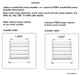
There is a large volume Jabsco seawater pump impeller that is almost identical to the F6B-9 impeller.
Parts supply people have been known to get confused on this.


Jabsco vs Johnson F6B 9 impellers.png

The heat exchanger was just serviced.

Hi Mark

The post got cut off some how, my apologies. My problem is that I installed an engine overheat alarm switch which triggers at 200 degrees to the left of the thermostat housing as viewed from the front of the motor.
If this over-heat alarm switch is installed in the intake manifold next to the OEM temp sender, and up-stream of the actual thermostat, I see no issues.

The motor runs at 140 Degrees at idle. While idling the temp switch is activating the alarm. Measuring the body of the temp switch with an Infra red temp gun it reads 192 degrees when it triggers which is ok.
A 200* alarm switch that is being triggered at 192* is probably not an issue. That's only an 8* differential.
The real question would be... "why is a 140* thermostat allowing for a 192* engine coolant temp in this area?"


The problem is that the factory temp sensor body located 8 inches away in the same passage is reading a 138 degrees.
what I have here is a 55 degree temp difference over the span of the thermostat passage in the intake manifold.
That would be the coolant cross-over area, and is upstream of the actual thermostat location.

I thought perhaps the rebuilder may have installed the intake or head gaskets incorrectly possibly blocking a cooling passage.
My machinist says it's not possible on a SBC.
I would agree with him.

Any help would be greatly appreciated.


Questions:

.... Where the "spent" seawater leaves the H/E and enters the exhaust manifolds, are you using the correct brass or bronze 90* elbows with a smooth interior transition?

.... Are the two same area hoses in good condition?

.... Is the Y fitting (that splits the spent seawater) equipped with the diverter web inside of it and is it in tact?
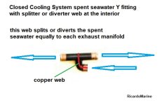

closed cooling system Y fitting w splitter diverter.jpg

.... Are the gaskets (between the manifolds and elbows) fully open at the seawater transfer ports?
Example only
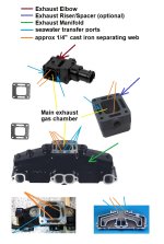
Exhaust manifold transfer ports explained.jpg


.
 
Last edited:
Jon, you can buy a coolant test kit that will show the presence of Hydrocarbons.
The presence of hydrocarbons in your coolant would indicate a possible crack or a failing head gasket.


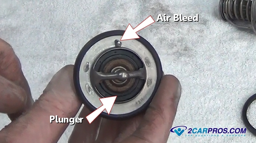
One other thought... does your thermostat flange have an air bleed hole in it?

Example only


air-bleed-thermostat.jpg
 
Hi Gang

This motor has a vertical heat exchanger that was supplied to the original motor which was a BB261a

Rick, I don’t see that valve that you displayed.

I don’t think the new T stat has a bleed hole.

The gaskets between the mans. and elbows are open.

The 90 deg. fittings at the exhaust manifolds are the cheap squarish ones.

Chris, I have a coolant gas test kit and will try it.

The alarm switch is installed to the right of the thermostat as viewed from the front of the motor.

I am at my wits end

Thanks

Jon Allen
 
...........
Hi Gang

This engine has a vertical heat exchanger that was supplied to the original engine which was a BB261a
The BB would have been an inboard engine...... of which is basically the same engine.


Rick, I don’t see that valve that you displayed.
That would be a Y fitting.... yes/no????
If so, that fitting has an internal web that splits/divides the spent seawater so that equal amounts will be sent to the exhaust system!
Are you able to post several good photos of your engine and heat exchanger for us?


I don’t think the new T stat has a bleed hole.
You can drill one into the flange ...... very small..... perhaps 1/16".
The ones with the factory air bleed will have a tiny crimped metallic piece in the hole.

The gaskets between the mans. and elbows are open.
Good.

Question:
Where your 95mm wet exhaust couplers run from the Elbows to the top bend of the Y-pipe, by chance are they being clamped over the Elbow's scalloped areas?

NOTE: The OEM 95mm couplers are always too short...... Not occasionally short...... ALWAYS too short!
When too short, they end up being clamped and compressed into the scalloped area, restricting spent seawater!

The 90 deg. fittings at the exhaust manifolds are the cheap squarish ones.
I would look into a pair of 90* elbows with a more smooth transition..... especially with the larger volume F6B-9 seawater pump.

Chris, I have a coolant gas test kit and will try it.

The alarm switch is installed to the right of the thermostat as viewed from the front of the engine.


I am at my wits end

Jon, let's start over, and with 4, 5 or 6 good photos..... and your credit card number! :D
 
Hi Rick

The exhaust elbow exit hoses are secured correctly and the clamps are not tightened against the scalloped area.

I learned this from you on a previous post!

I will drill a small hole into the thermostat flange if not so equipped.

Will be changing out the manifold inlet fitting with the smooth progressive cast bronze ones.

In your opinion, how much flow restriction in percentage exists between the two styles?

I will snake a coat hanger thru the crossover via the thermostat opening to the cylinder head as maybe someone got too aggressive with RTV around the ports.

I wil try to get some photos to post.

Thank You

Jon Allen
 
Back
Top