Logo

40 HP Evinrude, Model VE40TLESR, battery charging system not working

Ernie84

New member
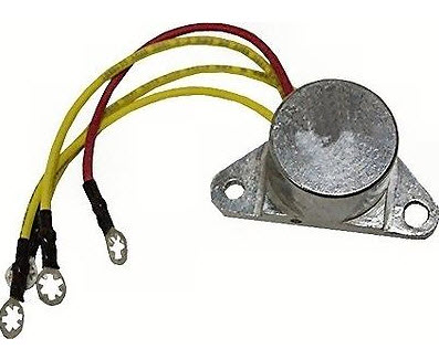
I have diagnosed part of the problem is that the voltage rectifier has the Red wire fried.
I want to check the Stator Assembly while I am at is to verify it has the correct resistance.
What is the correct resistance value for the 3 wires on this assembly (Yellow, Yellow/Gray, Yellow/Blue)?
Thanks for any help.
 
Don't have the specs for that exact model, but typical would be about half an Ohm between any two stator wires and infinity between any wire and ground. (All stator wires disconnected for test)
 
Thanks for your help. My readings are between 4 and 5 ohms, so I assume my stator assy., is shot too. Do you have any idea where I could get the Stator Assy. # 0584341 (which replaces # 0583650)? It is no longer available as a new item.
 
Thanks for your help. My readings are between 4 and 5 ohms, so I assume my stator assy., is shot too. Do you have any idea where I could get the Stator Assy. # 0584341 (which replaces # 0583650)? It is no longer available as a new item.

In theory you should see very low resistances. 0.5 ohm is the figure I have noted for my 6hp. Id not expect the stator coils on other engines to be vastly different but low resistances are difficult to measure accurately due to the resistance of the connections

However I'd expect to see either a low resistance or an open circuit. For that reason i would not rush to replace the stator coils without further diagnostic testing

If the red wire coming from the rectifier is fried Id think it is very likely that the rectifier is fried too ...possibly due to connecting the battery with the polarity reversed ( that will fry a rectifier quicker than you can utter a rude word or two.)

I would test the rectifier .

MarineEngine list both of the part numbers you mention as unavailable Maybe Sierra or CDI electronics can supply an alternative
 
Thanks much for precise information. Now all I need is a replacement stator assembly. Either PN 0583650 or the superceded PN 0584341. Any help finding one would be greatly appreciated.
 
Does anyone know the proper procedure and values if there are any to check the rectifier # 0581778?

Disconnect the rectifier completely

0581778.jpg


Using a digital multimeter set to the diode test range

Clip the positive meter lead to the rectifier's red lead and the negative lead to each of the yellow leads in turn. You should get no readings on the meter

Clip the negative meter lead to the red lead and the positive lead to each of the yellows in turn. You should get three readings of about 400-500 (i dont know the exact value)

Clip the positive meter lead to the metal case and the negative lead to each of the yellows in turn You should get three readings of about 400-500

Finally clip the negative lead to the metal case and the positive lead to each of the yellows in turn. You should get no readings


If you get the above results........It indicates the rectifier is good
If you get anything else the rectifier is bad
 
Thanks much. When I did get readings they were in the .400 - .500 range. So I assume them to be correct.

Yes I should hve expained in a bit more depth. 400 to 500 mV or 0.4 to 0.5 volts It depends on the meter ( both of mine read in mV )
 
Back
Top