So I connected most of the stuff back to the bell housing and it wasn't easy. I installed all the bellows on the gimbal first including the shift cable, used the adhesive. It wasn't extremely difficult but anyways, have to be careful. I installed the oil hose which in my opinion should be installed first so that you have room to push, that's pretty difficult to do. I used a ziptie to secure it.

The water hose you see mounted had to be removed as it has to go on the bell housing first. Than I put it in and had to spray WD-40 to get it to slide in and make sure already have the clamp in there before the hose.
then came the bellows and I installed the exhaust shaft first, adhesive on bell housing also, and work it with the special tool. First 2 times I had to redo because it came out upon tightening it. But the 3rd time I made sure it was all the way up and I do think the adhesive also cured for the 10 minutes the manual recommends to wait so it is not tacky, and it held. Pain in the ass and might require 2 people and lots of light and patience. Tighten from below and the little tab/clip has to go underneath because otherwise when raising the motor it could snap out. That clip if original is bolted on to the bellow. I saw it in the numerous videos I watched.
 This is a picture from below.
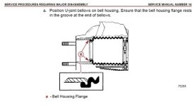
So now I am at the main bellow and in the manual it says to slide it to the second groove. I mean there's a raised lip on the bellow and a groove on the housing.

I don't see 2 lips.


And then to hammer the ring sleeve on does the bell housing have to be attached to the gimble?
Anyways that's where I am at right now
The water hose you see mounted had to be removed as it has to go on the bell housing first. Than I put it in and had to spray WD-40 to get it to slide in and make sure already have the clamp in there before the hose.
then came the bellows and I installed the exhaust shaft first, adhesive on bell housing also, and work it with the special tool. First 2 times I had to redo because it came out upon tightening it. But the 3rd time I made sure it was all the way up and I do think the adhesive also cured for the 10 minutes the manual recommends to wait so it is not tacky, and it held. Pain in the ass and might require 2 people and lots of light and patience. Tighten from below and the little tab/clip has to go underneath because otherwise when raising the motor it could snap out. That clip if original is bolted on to the bellow. I saw it in the numerous videos I watched.
This is a picture from below.So now I am at the main bellow and in the manual it says to slide it to the second groove. I mean there's a raised lip on the bellow and a groove on the housing.
I don't see 2 lips.
And then to hammer the ring sleeve on does the bell housing have to be attached to the gimble?
Anyways that's where I am at right now
Last edited: