Logo

Hydrolocked in the parkinglot

I encourage you to support the hosts of this website by buying from their online store. This site has already saved you hundreds of dollars, so please return the favor and buy here if you can. Their price for the same kit is very competitive with other vendors:
http://www.marineengine.com/newparts/part_details.php?pnum=SIE18-3147

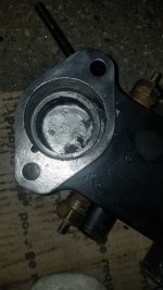
Let's work on the shift adjustments after you have it all back together.
Didn't know they sell parts, I will check out the prices. Thanks.
 
Ok so I opened up the lower drive and here is the water impeller, it looks really odd to me but have never seen another.
20210205_114948.jpg20210205_114957.jpg
There are pictures of the area where the pump goes
20210205_115036.jpgView attachment 2602220210205_123625.jpg
As you probably didn't expect I forgot that there was a bolt at the outer end and by forcing it the casing I cracked on side of it. I assume I can get it welded since there is no sealing there or much pressure? It's aluminum right? Here is my great accomplishment:
20210205_124551.jpg20210205_124507.jpg
 
So while I am here do you guys recommend replacing anything in the gimbal and transom area? I need the big gasket and an 2 inch O-ring for sure.
20210205_123140.jpg20210205_130128.jpg
 
So while I am here do you guys recommend replacing anything in the gimbal and transom area? I need the big gasket and an 2 inch O-ring for sure.
View attachment 26026View attachment 26027
From my keyboard the bellows look good no water ingress stick your hand in there and feel the gimbal bearing , turn for smoothness. If rough replace.

yes you can weld the outdrive it is aluminum. Find somebody who has tig welded these or a prop shop can fix it cheap. Also get a #14 manual (google it ) for merc alpha gen ii outdrives, watch some youtube videos on impeller replacement etc. not to kick yiu while your down and i have broken some stuff over the years but you must have beat the hell out of it to separate the two haves enough to crack it. Plenty of free tutorials out there...
the water pump impeller looks normal no pieces missing .

this site has some of the best parts drawings out there offers both oem and aftermarket parts so u can compare costs. In the upper left of this page click on parts icon , select mercruiser sterndrive, when the page comes up you can type in your engine, transom, or drive serial number will come up with correct parts for each.

get the outdrive gaskt and it will have the orings you need including the big sq one that gets glued into the end of bellhousing/ bellows. If you dont glue it in place it wont stay in when you put the drive back
 
When you reassemble don't forget the little drive key that locks the impeller to the shaft. Doesn't pump well without it.
 
When you reassemble don't forget the little drive key that locks the impeller to the shaft. Doesn't pump well without it.
So the water pump is supposed to be bent like that? I already ordered another set
So the impeller has to be bent inside like that? So it must not have been the impeller or this water pump at fault, for not getting the water to glow through.
 
As I read thru your update it seams to me you have done a ton of work and spent a ton of money on new parts without any troubleshooting.

Also I dont see anything pointing to a root cause. Did you find one?


1. You run this raw water cooled Alpha one gen II in salt water.

2. The engine circulating water pump has a Bronze Bi-directional impeller. Even with a weep as found it has not completely failed and was not your problem.

3. The impeller in the Gen II out drive has a very long life. It is shortened considerably when used in salt water and is typically recommended to be replaced every 2-3 seasons. The shape you ask about is perfectly normal.

4. Main area of concern around outdrive impeller (other than the impeller) is the thin aluminum dam and rubber insert just behind the dam. If the dam erodes and or the rubber insert is missing or eroded or compressed, it can possibly allow hot exhaust water to enter impeller. Yours looks good.

Once you have this all back together, If you want to confirm good water flow, remove the incoming water hose from thermostat housing. With the water muffs attached and water on, start engine. Confirm a lot of water coming out of incoming disconnected hose. If you get a nice volume of water, ( several gallons per minute) shut off engine. then you are ok to reconnect hose to thermostat housing.

Note: this is best done in the water for a real test. The water hose pressure will push water without engine/drive running.........

You can run the engine for several minutes with no water before it gets warm enough to be concerned, just dont run it to long and keep an eye on temp gauge.

As you are replacing the thermostat with a new one, I would think with all the other new parts you should be good to go.


My opinion,
based on salt water use I would think the first suspected failure would have been the thermostat stuck closed not allowing water to flow in/out of engine block.
replacing the impeller is a good thing even if it was ok. Good to have a good base line after all this work.

Report back when you get it all back together and running.

Hi and thanks for the pointers. I always try to diagnose before buying stuff but got carried away because I want to assure safety off the coast. The original problem was the hydro lock. Water in all 8 plugs out water flowing outwards, changed oil 2 times sprayed stuff in cylinders to protect from corrosion. Idle not holding. So I rebuilt the 2bbl carb and got idle back running great off water but no water going through gauge went up. I got water at the upper blue plugs but none at the lower. Boat has only been in saltwater once. flushed properly after. when the hydro lock occurred found lots of water up to the starter in engine bay. Starter replaced because plastic gear broke at the planetary wheels. Compression done
registered 165-170. This boat has never had much work done but has not seen that much water either. That's the story in a nutshell.
 
When you get water in ALL cylinders, that is cause by backwards flow from exhaust 99% of the time.

There can be many reasons for this to occur. a few are below

1. when you shut engine off it "Diesels" and does not stop running and can actually run backwards for a few revolutions causing the water in exhaust to be sucked in through valves to all cylinders.
a. this is typically due to bad timing (to advanced) or
b. carb running very rich..............Which you point to as the carb was exhibiting running issues.
c. Engine temp is to high causing ignition to continue after key is turned off causing the "Dieseling"

2. You are running hard in gear and come to a stop quickly and the wake behind boat catches up to boat and over powers the exhaust and forces water backwards in the system so to speak causing a similar issue as #1 and water gets sucked in to ALL cylinders. This is not as typical in a I/O configuration when the exhaust exits the prop, more that likely when you have thru transom exhaust.

Yes but mine hydro locked in the parking lot long after it was pulled from the water. And I already did the flush in between the events. There was some torrential rain and the engine area was totally filled with water. I don't know if the water also got in through the carb as the cover and flame resistor were removed at the time as far as I can remember.
So backwards flow is unlikely in this case because it worked after being on water.
 
Was trying to figure out how to take out the old one, I think just pulling on it should do.
Also the thermostat housing that I cleaned do you guys paint the inside on it where the metal is exposed?

20210209_174022.jpg 20210209_174032.jpg
 

Attachments

  • 20210209_174017.jpg
    20210209_174017.jpg
    317.2 KB · Views: 46
""""I don't know if the water also got in through the carb as the cover and flame resistor were removed at the time as far as I can remember.""""


Well if on the trailer and this occurred when NOT running or right after shut down then I think you may have found the reason.......All eight will fill up if rain water gets into carb........That may explain it.............


Again, It is impossible for water to get into all eight cylinders except under the conditions i mentioned and if what you think may have happened, happened.

There would have to be a Gross leak at BOTH SIDES at manifolds/elbows at the same time for water to get into all eight. NOT LIKELY!
A gross leak at intake to heads allowing water to get into intake runners on BOTH SIDES at the same time.............NOT LIKELY

Otherwise your guess is as good as any.

Yeah it was very odd the boat was running great, nothing on the water, carb great, and on the trailer the flushing went on great 2 times after the last offshore. And then all of a sudden lots of water in the engine area and all 8 cyls full of water. I always suspected the heavy downpour. nevertheless I was careless to leave it opened. It won't happen again that's for sure. Now I am waiting for all the parts to arrive and I will do the gimble rubber, the cable, water pump, circulating water pump, thermostat. I have to make sure I do it all right especially the upper lower drives, raw pump, cable etc. Wanna make sure everything has the right grease and the right adhesive and or sealant.
 
Should I mess with the gimbal steering arm swivel? I know it's a pain to remove and there is a certain way to tighten it. The original might be corroded I don't know but looking at the stuff I took out which doesn't look so bad I would rather not. What say you?
GIMBEL RING DISASSEMBLE - YouTube
Better not
 
Last edited:
I would check inside for evidence of the seal leaking at the steering arm swivel pin (inside behind engine on tramsom housing) and play between steering arm, pin, and gimbal ring. If no evidence of leaking and no play leave it alone.
 
No play the whole are including bellows are really good and the bearing is perfect. This boat has not been used much. If you look at the pictures I took there is no water intrusion anywhere. I wonder if I should just leave it alone for now and wait awhile. I am just pissed off that the alignment tool I bought didn't arrive.
 
No play the whole are including bellows are really good and the bearing is perfect. This boat has not been used much. If you look at the pictures I took there is no water intrusion anywhere. I wonder if I should just leave it alone for now and wait awhile. I am just pissed off that the alignment tool I bought didn't arrive.
If the rubber parts look good I'd leave it alone, tjust do the water pump and base as Chris mentioned, and get some one to fix the crack in the upper (prop shop if you can find one local). And keep the carb cover on and drain plug out when on the trailer....
 
You have a Alpha Gen II

It appears you trailer vs keep tied to a dock all summer.

The steering arm itself to the steering pin rarely wears out. What wears out the the gimbal ring to steering pin

It is important to keep the two bolts that tighten the gimbal ring to steering pin adjusted/tight WHEN NEEDED ONLY and this is determined by the side to side play of the drive to the steering pin. If the drive and pin appear to be tight and they move 100% at the same time you are good to go. The two bolts can only be tightened so much then there is no more threads so this is not something you do unless needed!!!!

Top of ring has grooves and item 21 x 2 are the bolts. Notice they show a shoulder line on the bolts. This is the extent of the threads.


http://www.marineengine.com/parts/m...up/0l100040-up/gimbal-ring-and-steering-lever


One last note, If you ever need to replace the pin and ring, Do it the correct way, Remove the engine to get access to the pin nut and replace without drilling holes in the transom assembly. That kit is better suited for busy marina's when time is a $$$$ factor. besides they have the huge pipe tap needed to thread the holes you drill to install the plugs. Makes the drive look like crap.
 
I took out the bell housing and I got the the bearing which didn't budge with the slide hammer. Tried and tried and finally ordered a different type bearing tool
20210212_154058.jpg
Just for kicks I inserted a vacuum extension pipe in the engine where you check alignment and voila
20210212_173612.jpg20210212_173619.jpg
Am waiting for the new tool to remove the damn bearing. The slide hammer was worthless. This is the new one:
Amazon.com: Sierra 18-79820-1 Gimbal Bearing Puller for Mercruiser/OMC/Volvo: Automotive
Also got the seal that's behind the bearing don't know if it's needed but hey it's a party.
Amazon.com: Sierra International 18-2094 Marine Oil Seal for Mercruiser Stern Drive: Automotive
Hope tomorrow the bearing will be out.
I have not found anything corroded in the bell housing area so I hope all this and the circulation pump and thermostat solve the circulation problem in and out of the engine.
I also hope when I changed the flappers I didn't put them on backwards. I don't think there is a way to do that and I always double and triple check.
 
The answer to your slide hammer is to have a much heavier slide made.

I Made my own slide out of steel and it weighs over 10 lbs.....two to three slams and almost any bearing will come out. I have done hundreds of gimbal bearings and never had any issues


41d5FsA0J9L._AC_SL1013_.jpg
 
Last edited:
A hunk of 2x2 angle steel, a long threaded rod and a big socket works great. In my case, I used a hunk of 2x2 aluminum that my dad scrounged a billion years ago. I already had a hole in it so I was golden. 2x2 goes across the gimbal housing. Rod goes down thru bearing and thru big socket (or whatever). Nut on each end of threaded rod (duh). Rachet away until bearing pops out.
I suppose you could also use a hunk of 2x4, as the effort to pull the bearing isn't all that great that you'd bust it.
This method is slower and more fiddly than the slide hammer method but it is very much cheaper than a new special tool

Shown in my B3 conversion thread here:
#44

made a similar puller out of a 1/2” threaded rod, used a couple of fender washers ground down the OD of washer so it would fit in the bearing, used a 2x4 across the bellhousing drive opening. Slide the nutted washer through the bearing and push it out to catch on the bearing. The washer can slide off while pulling, but basically works and is made out of stuff laying around..
 
Yeah that's the one I got and it took 2 minutes. Waisted my time yesterday with the little slide hammer.
20210214_141541.jpg20210214_141643.jpg
My question now is since the oil seal came out also when I put it back is it pushed all the way against the back of the designated space right? See picture
20210214_152504.jpg
Also I took out the trim switches one was really dry outside(port) the other had grease all over and also broke up in pieces. When I put the wires back does it have a positive and a negative or it doesn't matter?
20210214_152650.jpg
 
Installed the seal and bearing, which is the new one with no repacking option.
20210215_162620.jpg
[FONT=&quot]I also already got a new oil hose in and zip-tied, and the shift cable through.[/FONT]
[FONT=&quot]I am changing the trim switches tomorrow.[/FONT]
[FONT=&quot]Do the wires have positive and negative or it doesn't matter which of the 2 I connect to the designated port and starboard.[/FONT]
[FONT=&quot]I will get the bellows installed and I read that only gimbal side get the adhesive is that true or both sides for the 2 large. I know the shift cable gets one side.[/FONT]
 
Switch on left side (when looking from back towards front of boat) is the trim LIMIT switch. There should be near the trim pump a three wire connection in a small black connector holder. The wires feeding it are Blue/white (2) and Purple/white. No polarization. The switch is simply ON/OFF

Sender on right side is trim position sender, It is a variable resister that feeds the trim gauge. There is typically somewhere on the engine the two wire connection for this. It location varies based on model and who may have worked on it.- No polarization-Variable resister.

Short shift cable adjustment as follows


Trim outdrive up 2 inches from all the way down.
Take keys out of ignition!!!!!!!!!!!
Have a second person stand at the prop.
You, remove the short shift cable from the shift bracket on engine. The cable that goes to the outdrive.
After the cable has been removed, push the plastic cable end all the way in and hold in place while prop is being spun C’Clockwise..
Have second person rotate prop counter clock wise until the prop is fully engaged and wont turn anymore. Maintain light effort on shift cable plastic end pushing it to keep forward engaged.

Measure the distance from the center of the brass trunion/barrel to the center of the round mounting hole in the plastic end. Adjust trunion/barrel to make that distance 6 inches. no more no less!

In cases where the shift cable is old but still works well you can adjust this dimension to 5 15/16”. NO MORE.

Put shift control handle in forward FULL throttle position.
Remove the control shift cable from shift bracket at this time.

Install short shift cable back onto bracket at this time.

Take the shift control cable and adjust the trunion/barrel so it fits perfectly back into the shift bracket.
Before completely installing it turn the brass trunion/barrel 4 complete turns away from the plastic end and reinstall into shift bracket and install the nuts but do not tighten at this time.

Now put shift control handle in the neutral position.
Have second person spin prop, it should spin freely.
Put shift control into the forward detent position at ~ 10:00 position. NO FUTHER.
Have the second person rotate the prop counter clockwise. You should have solid engagement with no ability to continue to turn the prop.

Now shift back into neutral. Prop should spin freely with no clacking or clunking.

Now shift to reverse to the 2:00 o’clock detent position NO FURTHER!!

Have the second person spin the prop clockwise.

If you have positive engagement with no clunking or jumping out of engagement, you are done.
 
Back
Top