Logo

2007 Honda BF 20 tilt trim switch?

Tedmarx38

New member
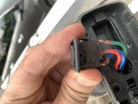
The up/down switch is on the throttle lever by the instrument panel. I’m getting zero response from it and the easy problems like the fuse and and battery charge all check out fine. The connections on the switch look corroded and while the connections seem solid, I thought about buying a new switch but can’t find it anywhere. It sits in the top of the lever and is very small, so to disconnect the three wires I’d end up destroying the switch. The wires and connections in the switch are not touching each other so there’s no short there.

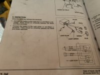
I don’t have a volt meter and am reluctant to delve into the relays, unless you think that’s absolutely necessary (I have the shop manual but the electrical stuff is a bit tricky for me.). Any thoughts on what I might be missing will be appreciated. Everything else - starter, lights etc work fine. Thanks.
 

Attachments

  • F5D3821C-28F2-427F-9C15-A45E4D643129.jpeg
    F5D3821C-28F2-427F-9C15-A45E4D643129.jpeg
    84.9 KB · Views: 22
Yeah, it’s a pontoon and it’s tough to tell what components the outfit that built it used. I’ll try connecting the wires directly as you suggested. Thanks.
 
Assuming the tilt works when you short those wires together, if you are VERY careful, you might be able to pry that rocker out of the switch to give you access to the contact points that are likely dirty/corroded. A little cleaning and you could be back in business!
 
Thanks - yeah I’ll give it a try. Worst case if that’s the problem is I’d pull the wires out of the gear shift and install a switch on the instrument panel.
 
Hi,
DO NOT FUTZ WITH THE SWITCH!

These have a "tilt relay module" under the hood. It's a black, rectangular box about an inch wide by two inches long. It is mounted to the rear and slightly to port near the "tool tray".

My experience with these is that, because of flexing, the wires going into this sealed unit tend to break since Honda didn't build in enough slack for the connection.
About 90% of "dead tilt" problems on the 20 are due to the broken wires. I'm betting you find this to be true.

In almost all cases there has been just enough wire left sticking out to allow for a solder job. Although, I think I've had one or two I couldn't save. If you're not a good hand with a soldering iron, you probably have a friend that is. Add a bit of extra slack while your at it and reinforce the wire by proper heat shrink coverage of the repair.


No reason that you shouldn't have a volt meter. You don't necessarily need a highly accurate one and there are plenty available that "will do ya" for this sort of stuff that aren't expensive at all.

Good luck
 
If you don't find broken wires at that module you will probably need to troubleshoot the system from the tilt motor forward. Although, since you've got the switch in hand, there's no harm in shorting the white/blue (center terminal) to either of the outer terminals one at a time as Alan has suggested.

It's just a more logical approach to start at the motor end normally. You can unplug the motor and test it independently from the system by supplying power and ground using jumper wires. Ground the green wire and apply 12volts to white or blue one at a time to see if the motor will run.

If the motor works properly then I highly recommend that you do get an inexpensive voltmeter (digital preferably) to continue checking the circuit to find where you may be losing power. A voltmeter will also allow you to do voltage drop testing (google it) to find compromised wires or a bad ground condition.

If you have the authentic Honda shop manual, then you have the accurate wire diagrams needed to find your test points.


Good luck.
 
Thanks for your help so far. It’s definitely not the switch as bypassing it yields no response. One question: I assume the 20 amp fuse on the motor that protects the starter etc also protects the tilt motor....there’s no another fuse hiding somewhere?
 
No other fuses. The 20amp CHARGING circuit fuse is the only one for this outboard.

It would be good to know if you have proper volts at the center terminal (white/blue wire) since you have the switch out. If there's a Harbor Freight near you, a cheap voltmeter is a wonderful thing to have when doing this type of work. But I'll try not to belabor the subject anymore.

Your instincts about the fuse are good though as that fuse feeds the white wire that powers the charging circuit REGULATOR/RECTIFIER. And, it so happens that the tilt switch center terminal is fed by the white/blue wire from the regulator/rectifier plug which would ultimately be one of your test points for this issue. You WOULD NOT want to use an incandescent test light at the rectifier because it is solid state. So don't go there or you could damage it.
 
One quick thing you might try is locate the parallel 3 wire harness for the tiller control tilt switch under the hood. Same colors: white for power with light blue and light green wires going to tilt relay module.
If yo can find those you might try the same thing yo tried at the switch. White (power) to either the light blue or light green wire. If it works, it won't tell you where the problem is but it will tell you what it's not.
 
I removed the power tilt relay box and tried the test recommended in the manual. (1) connect the battery to light blue (+) and black (-), and check for current between the white and blue terminals. No current (bought a multi meter and checked various ways. (2) connect battery to light green (+) and black and look for current between white and green. Nothing. I checked all the wires to the relay box and they are not broken. I’m curious as to how often the relays go bad on these as I’m tempted to get a replacement at this point rather than continue monkeying around as it seems that’s the issue - assuming they snot manual test outlined above is accurate. Thanks.
 
I did note some ticking and jingling in the relay box when I hooked up the battery, but again, not power through the circuits Honda said to test. Thanks.
 
Clearly that middle/red wire on the switch is going to need 12v before it's going to work. If it were working one way (up for instance), but not the other, it could be the green or blue.

So, no power, or broken wire assumption still works....
 
This should be pretty easy. Wait until you get something tricky to REALLY start hatin.... like water mixing with your oil for instance.....
 
If you determine that the T/T motor has failed, come back to me at [email protected]. I have a list of API DC motors that are a direct replacement for the Honda motors and cross references to the Honda part numbers. The motors are less than 50% the cost of the Honda branded motors and work just fine. I Installed an API replacement on my BF 225 in 2011 and it's still working fine.
 
UPDATE
Looks like I’ve limited out on my mechanical skills. I tried direct wiring the motor (I think I did it right but I’m not sure) and got no response. I honestly can’t ascertain where the motor even is despite using the shop manual and parts diagrams - does it sit vertically inside the drive shaft area or immediately under the hood? Margetics, my normal go-to shop is backed up 2-3
weeks so if anyone can reco someone via email ([email protected]) in the Pittsburgh area ... ideally north of the city I’ll appreciated. Thanks all for your many tips — I gave it my best shot but need to pause before I cause damage.
 
Last edited:
Updated update

turns out I didn’t directly wire the motor correctly earlier today. I checked it and it does run in both directions. Appears it’s the relay then that needs replaced. Thanks again for all your help.
 
Well, at $177 + shipping (item #19 in link below) let's hope you're correct.

But I'm not convinced at all. While anything is possible, I've never seen one of those modules fail....other than the wires breaking. Additionally, IF it did fail, it would be highly unlikely that it would fail to operate the motor in BOTH directions. The reason I say that is because it has TWO separate relays inside that "potted" box assembly. The motor not powering up in either direction would mean that both relays have failed simultaneously. I don't buy it.

I still believe that you have a connectivity issue causing this problem.

Look at item #23 in the parts illustration. That is the ground for the module. I think that the ground side of the circuit should be thoroughly investigated and all grounds, including that one, be cleaned and verified prior to ordering a new relay assembly. If you would take the time to read up on BASIC electrical circuitry and a VERY USEFUL test procedure called "voltage drop" you could get the most out of the meter you just purchased and likely save yourself some serious coin here.

That relay module can be EASILY tested using that meter of yours with just a WEE BIT of rudimentary "boning up" on circuits. Example: Google "how an electrical relay works". Complete with colored illustrations as well as animated YouTube videos.

Just sayin'.

Good luck.

https://www.boats.net/catalog/honda...-later/wire-harness-regulator-starter-cable-2
 
Thanks for the tips. I did the diagnostic test per the photo and couldn’t find any current through the box. It ticked when I added power but there wasn’t any continuity in either of the outlined combinations. I plan to hook everything back up to the relay and try the switch again just for the heck of it. Does the test outlined in the photo make sense to you? Looking at the way the switches inside the relay operate it seems correct, but I agree that it’s odd to have both directions fail.
 

Attachments

  • 4BE7DD5C-8E2C-4607-B577-5A61F527F00B.jpeg
    4BE7DD5C-8E2C-4607-B577-5A61F527F00B.jpeg
    75.5 KB · Views: 29
Last edited:
Did you have current TO the box? 12v and ground? Without that, there's no way the box would ever pass any test.

The ground wire is fastened to the block. Have you had that off and inspected/cleaned it?
 
Did you have current TO the box (white wire)? 12v and ground? Without that, there's no way the box would ever pass any test.

The black ground wire is fastened to the block. Have you had that off and inspected/cleaned it? The white wire should always indicate the presence of 12v.
 
JGMO saved 180 bucks and counting and Alan, yes, I had power to the box when I tested it. However, I was looking for voltage and amps but after looking at the diagram more carefully, I see that it’s simply continuity that I need to check. And, that test checks out so the box is fine. I can hear the switches close in both directions when powered up.

So I’m back to the wiring problems although I’m first going to reattach the box and try to remote switch again, since now that I know both it and the motor are okay, it’s possible that I dislodged some gunk that could have been the issue, with all this tinkering around I’ve done. Low chance though - it’s very clean under the hood and no signs of corrosion. I’d appreciate some help on the wiring diagram per the box I drew on the attached with the star beside it. I’ve consulted several online guides to symbols but I’m not finding the ones shown here. This part of the diagram shows light blue, light green and white/black branching off and apparently terminating. I can’t figure this out as I’m not able to identify what the accompanying symbols mean. Thanks. C41AE36C-70F9-44D0-9B96-FCBFB4C31E02.jpeg
 
Last edited:
Just stop saying "I can't".

It's obvious to me that you CAN!

You figured out that confusing module test all on your own to determine the "box" works so I have complete confidence that you will get this fixed.

You're in the learning process and being kept from using your boat like you want but, when you're done, it will feel GREAT!

And you will own two things that you didn't have before....
...a very useful meter and.....more importantly....KNOWLEDGE that you can build on and use time and time again!

Stay after it! You're on a roll!
BE POSITIVE!
 
JGMO saved 180 bucks and counting and Alan, yes, I had power to the box when I tested it. However, I was looking for voltage and amps but after looking at the diagram more carefully, I see that it’s simply continuity that I need to check. And, that test checks out so the box is fine. I can hear the switches close in both directions when powered up.

So I’m back to the wiring problems although I’m first going to reattach the box and try to remote switch again, since now that I know both it and the motor are okay, it’s possible that I dislodged some gunk that could have been the issue, with all this tinkering around I’ve done. Low chance though - it’s very clean under the hood and no signs of corrosion. I’d appreciate some help on the wiring diagram per the box I drew on the attached with the star beside it. I’ve consulted several online guides to symbols but I’m not finding the ones shown here. This part of the diagram shows light blue, light green and white/black branching off and apparently terminating. I can’t figure this out as I’m not able to identify what the accompanying symbols mean. Thanks.
View attachment 24436
 
Not sure where you are running into trouble.

The white wire is power 12v+ coming from the fuse.

Black wire is 12v- coming from a ring connector fastened to the engine block.

Green and blue go to the motor. These are the heavy gauge wires.

Lt. green and lt. blue are coming from the remote switch(s).

SO-
If you hear a click in both directions (up and down) it's fair to assume the white wire, the black wire, and both the lt. green and lt. blue wires are all good to go. That covers a good 75% of the possible issues that are good to go!

It leaves the motor, and those 2 heavy gauge blue and green wires being powered by the relay.

Depending on which way the remote switch is being operated the on/off functions of the heavy wires AND which polarity they have. So they are turning power on and off AND switching positive and negative polarity to run the tilt motor in both directions, depending on if you have the remote switch in the up or down position.

There's a pretty good sized connector between the motor and the relay. If you take that apart, you should be able to check for power and polarity coming from the relay. That's the last stop. If those are checking OK, the other side of this connector leads directly to the motor. If the motor has check out already, I'm not seeing how there could be an issue.
 
Back
Top