Logo

Troubleshot tachometer?

Set multimeter to AC volts. Connect black to ground and red to tach signal wire. Start engine. Should see same on multimeter as tach.
Test trim sender should read in ohm on multimeter. Should go up and down in value as you operate trim 33 to 240 ohm
 
o2batsea;682651[SIZE=3 said:

Test trim sender should read in ohm on multimeter. Should go up and down in value as you operate trim 33 to 240 ohm
[/SIZE]

Not a good idea to use an ohmmeter on a powered circuit... Move the drive, but shut power off before measuring ohms.
 
I measured V on the trim sender and the sender seems to be working, the V changed when tilting up and down.. Think something is wrong with the gauge.

Guess I have to use Hz multimeter to test the tachmeter
 
If you are getting an AC voltage at all ( in the volts range, not mv) , then the "sending" portion of the tach signal system is OK... no need to measure HZ. The output to the tach is not true AC, but rather pulsing DC. At idle it should display on the ACV scale on the order of 3VAC.
 
Ok! Guess I have to buy a new tachometer then.
But it seems that the Teleflex arctiv silver white tachometer with hourmeter is very hard to find.
 
QUOTE=Bigdrago;682602]Hi.
Is there a way to troubleshot the tachometer and trimindicator somehow? Mercruiser 1.7 dti.
View attachment 23631
[/QUOTE]


I had posted a kind of similar question with a multi-gauge I had where the tach stopped working. I found a couple forum posts online (not here) with some details of using a power supply and a function generator feeding a square wave into the signal input of the tach. The circuit of the tachometer is pretty simple with a divider chip that just does the math based on what the tach is set to.

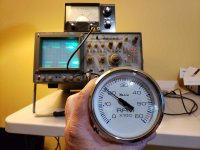
I ended up trying this method to test my tach but until I took the gauge apart, I had no way of knowing the needle was stuck stiff in position and no attempt to lubricate was going to help. Anyway I ended up ordering a whole new set of gauges and am currently waiting on the dash material to arrive as the dash will need to be redone to fit 4 inch gauges instead of 5 inch. I was still curious and wanted to see if the 9+ volt output of the function generator would drive the tach. Here is a picture of the test set up. Once I hit close to 7 volts peak to peak square wave input into the tach, it responded and would vary with the output frequency of the test generator. The 12 volt source I used is a 19 amp hour battery I keep on my test bench for this kind of thing.

gauge-test.jpg

Some meters have a frequency counter function which I find useful for this kind of testing.
 
Last edited:
Back
Top