91 OMC King Cobra, 5.7LE Chevy
Just rebuilt carb, and reinstalled, changed fuel water separator. Motor started on first bump and bench settings were perfect. It idled as smooth, as good as it ever has. Measured 15-16 inches Hg vacuum and needle rock steady. Took it out for test drive and ran great. Opened it up to 4000 RPM @ 45-50 mph. Was ready for a great weekend. Wait for it...
Couple hours later, daughter wanted to go out, as soon as I started to throttled up, I could feel Engine miss and got progressively worse with more throttle. Engine sputtered and popped. I turned around Immediately. Did the following checks.
Fuel Pressure ~ 5 psi
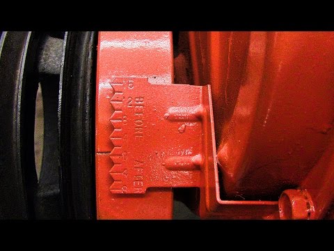
Base timing 8 -10 BTDC per manual
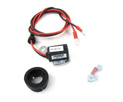
Checked Distributor and rotor. Noticed significant green corrosion all way around inside cap. I touched up all contacts with sand paper, shined up the rotor.
Pulled plugs, dry. A couple had some light carbon but I’ve seen them worse before rebuilding carb. Double checked gap @ 35 degrees. To no avail, engine miss still there and I noticed
a new noise. Sounded like a faint rattle. I thought it may have been rocker arm or something worse deep in the engine, but after listening more closely, I think it’s coming from the port side exhaust manifold. I read through the cooling system section in the manual thinking there might be some sort of flapper in there. I thought perhaps it might be contributing to the engine miss some.
I know that’s a lot. What do you think? I was so pumped that it was running so well. I should know better...
Do I check Fuel,Air, or Fire? I thought I had the fuel nailed with the new separator and carb rebuild.
Just rebuilt carb, and reinstalled, changed fuel water separator. Motor started on first bump and bench settings were perfect. It idled as smooth, as good as it ever has. Measured 15-16 inches Hg vacuum and needle rock steady. Took it out for test drive and ran great. Opened it up to 4000 RPM @ 45-50 mph. Was ready for a great weekend. Wait for it...
Couple hours later, daughter wanted to go out, as soon as I started to throttled up, I could feel Engine miss and got progressively worse with more throttle. Engine sputtered and popped. I turned around Immediately. Did the following checks.
Fuel Pressure ~ 5 psi
Base timing 8 -10 BTDC per manual
Checked Distributor and rotor. Noticed significant green corrosion all way around inside cap. I touched up all contacts with sand paper, shined up the rotor.
Pulled plugs, dry. A couple had some light carbon but I’ve seen them worse before rebuilding carb. Double checked gap @ 35 degrees. To no avail, engine miss still there and I noticed
a new noise. Sounded like a faint rattle. I thought it may have been rocker arm or something worse deep in the engine, but after listening more closely, I think it’s coming from the port side exhaust manifold. I read through the cooling system section in the manual thinking there might be some sort of flapper in there. I thought perhaps it might be contributing to the engine miss some.
I know that’s a lot. What do you think? I was so pumped that it was running so well. I should know better...
Do I check Fuel,Air, or Fire? I thought I had the fuel nailed with the new separator and carb rebuild.
 Well, I need to change my name to Murphy because his law always seems to apply. I dropped a tiny Locking washer of the electronic module post under Dist cap. I think it fell under base plate. I assume I need to now remove distributor to retrieve...?