Logo

Question about emptying carb during periods of non use

All of this is relatively simple!

Your goals:

#1..... Find a way to operate the electric fuel pump once engine oil pressure is achieved.
#2..... Find a way to momentarily operate the electric fuel pump prior to engine oil pressure.

Option for #1:
N/O low oil pressure switch in the loop.

Options for #2:
Start by-pass circuit.
or
Momentary helm switch.


Questions:
I know that Mark and I do not agree on the use of a relay. However, consider this;

Do you want to place an additional 4 or 5 amp load directly on your ignition circuit?
(keep in mind the length of the engine harness/hull harness (from helm to engine location) the small size of this circuit (length = resistance) and that there is an engine harness/hull harness connector (also adding resistance) in the path.)

Do you want to use a relay and NOT have the additional 4 or 5 amp load directly on the ignition circuit?
(the current required to trigger a relay is extremely low)


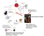
If both the start-by-pass circuit and momentary helm switch circuit are used, a diode would be installed in the S circuit to avoid any back-feed that would activate the starter motor. In other words, you do not want the momentary helm switch to activate the S circuit while simultaneously triggering the relay.
That would defeat the purpose of the momentary helm switch function.


Take a look at my updated schematic.

Electric fuel pump schematic.jpg

 
Last edited:
Rick please clarify for me. If I use a momentary switch then I was under the impression that I do not require a wire from Pin 85 to the Starter Solenoid. Is that correct? If so then why the diode? Sorry, I must have misunderstood.
 
...........
Rick please clarify for me. If I use a momentary switch then I was under the impression that I do not require a wire from Pin 85 to the Starter Solenoid. Is that correct?
Yes, that is correct.
However, there is nothing that would prevent you from incorporating both the "start by-pass" circuit and the helm located "momentary switch" circuit.
With both, you would prime the carburetor's float bowl with the momentary switch (several weeks of non-use, for example).
During daily use, the start by-pass circuit would suffice!

If you incorporate the momentary switch only, and if you do not interface the S circuit with pin #85, then the diode is not necessary.
In other words, there is no way that you would see a "back feed" from the momentary switch circuit to the solenoid's S terminal.
During the first start of each day, you may need to hit the momentary switch for a few seconds before engaging the starter motor.


If so then why the diode? Sorry, I must have misunderstood.
The diode will prevent the momentary switch circuit from back feeding and powering the S terminal.

Powering the S terminal will activate the starter motor, of which is what you want to avoid until the carburetor's float bowl is full.
In other words, the use of the momentary switch will eliminate the need for lots of cranking required to fill the carburetor's float bowl.


If you don't mind the extended cranking duration, then the momentary helm switch is not necessary.
In that case, you would simply incorporate the start by-pass circuit only.


In any event, if this was my boat, I would use the relay and keep the fuel pump's load from the Ignition circuit.

Your ignition circuit is old, it is lengthy, it passes through the hull harness pin connector, it is already powering the ignition coil, the helm instruments and possibly the choke's electric helix heating element.
When the relay is incorporated, the only additional load on the ignition circuit would be the very small load that would be used to trigger the relay via pin #85.
The power side of the relay (pin #30) and the Hobbs switch will receive power elsewhere.

When the relay is triggered, the output side of the relay (pin #87) will pass power directly to the fuel pump, by-passing the Hobbs switch.


.
 
Last edited:
Got it, makes sense. I intend to use the relay. I think my last questions (for now) are:

1) Can I use the "I" terminal on the Slave Solenoid on the engine to run the wire to the LOP and for the wire from "S" terminal to Pin 85? There is no need to run wire all the way from key switch is there? The terminals on key switch are already crowded with doubled up wires.

2) What is best way to physically piggy back two connectors on pin 85 of the relay? I have noticed some piggyback connectors on my switch bank at he helm, I assume I can find those online or in an electronics supply store.

FYI, I picked up non insulated butt terminals and adhesive heat shrink for this project as well as to correct some past wiring goofs.
 
Last edited:
............
Got it, makes sense. I intend to use the relay. I think my last questions (for now) are:

1) Can I use the "I" terminal on the Slave Solenoid on the engine to run the wire to the LOP and for the wire from "S" terminal to Pin 85? No need to run wire ll the way from Key switch is there?
Did you mean "R" terminal?
If either solenoid offers an "R" terminal, and if you use it, then the diode is not needed.
This is because the "R" terminal is isolated from the "S" terminal, and only becomes energized when the main contacts close.
Whereas the "S" terminal actually powers the solenoid's magnetic field winding.

In the event of a back-feed to the S terminal, the S terminal will activate the solenoid, of which will activate starter motor.
Whereas with a back-feed to the R terminal, it will not.

The terminal are already crowded with doubled up wires on the switch terminals.
Not following you on that one!

2) What is best way to physically piggy back two connectors on pin 85 of the relay? I have noticed some piggyback connectors on my switch bank at he helm, I assume I can find those online or in an electronics supply store.
You can crimp two wires into the same terminal, butt connect two wires together, or you can use one of these.
31A493_AS02

Keep in mind that you can also purchase a harness that will plug into the five pin relay.
images


You can also pick up a five pin relay connector with fittings, and then wire directly into it avoiding any butt connectors.
These fittings require a special crimp tool.
images


FYI, I picked up non insulated butt terminals and adhesive heat shrink for this project as well as to correct some past wiring goofs.


.
 
Last edited:
1) Can I use the "I" terminal on the Slave Solenoid on the engine "I" Terminal on the LOP?

Can I run S" terminal to Pin 85? No need to run wire ll the way from Key switch is there?

Did you mean "R" terminal?
If either solenoid offers an "R" terminal, and if you use it, then the diode is not needed.
This is because the "R" terminal is isolated from the "S" terminal, and only becomes energized when the main contacts close.
Whereas the "S" terminal actually powers the solenoid's magnetic field winding.

In the event of a back-feed to the S terminal, the S terminal will activate the solenoid, of which will activate starter motor.
Whereas with a back-feed to the R terminal, it will not.

There is no "R" designation in on the slave solenoid on mounted on engine. Although there is an "R" cast into the plastic on the starter motor solenoid, in post#33 you and Mark concurred that there is no terminal for the "R" designation.

attachment.php
attachment.php


Per your drawing below, I was planning to run a wire from the "I" Terminal on slave solenoid (its the top smaller terminal) on engine and run a wire to one side of the NO LOP.

Your drawing shows a junction in wire running from ignition key switch "S" terminal and the Starter Motor "S" Terminal. A wire runs from junction to pin 85.

I plan to run a wire from the "S" terminal on the Slave solenoid on the engine (which is connected to key switch "S" terminal) to pin 85. It is a convenient landing spot and prevents adding more wires to the key switch"S" terminal.

I would then piggyback a terminal on Pin 85 to run to the momentary Rocker. I would need to place diode on the wire connected to "S" Terminal on slave with cathode end of diode toward the relay.

Is this a feasible plan?

attachment.php

RicardoMarine said:
The terminal are already crowded with doubled up wires on the switch terminals.
Not following you on that one!
See pic of existing key switch with crowded terminals. This is why I'd prefer to avoid landing another wire on key switch and instead run the wire from "S" terminal on slave to the LOP.
attachment.php
 

Attachments

  • Rick drawing with slave imposed.jpg
    Rick drawing with slave imposed.jpg
    169.1 KB · Views: 96
  • Key Switch.jpeg
    Key Switch.jpeg
    198.5 KB · Views: 81
  • Boat Starter Motor Solenoid resized.jpg
    Boat Starter Motor Solenoid resized.jpg
    231 KB · Views: 82
  • Slave Solenoid.JPEG
    Slave Solenoid.JPEG
    195.1 KB · Views: 85
...........
There is no "R" designation in on the slave solenoid on mounted on engine. Although there is an "R" cast into the plastic on the starter motor solenoid, in post#33 you and Mark concurred that there is no terminal for the "R" designation.

You may find this terminal marked as "R" or "I" .
R = relay.
I = ignition.
Both perform the same function, and both are separate and are isolated from the "S" terminal and it's internal circuit.

"S" terminal energizes the solenoid's magnetic coil field of which in turn pulls the main contacts closed.
The "R" or "I" terminal becomes energized ONLY when the main contacts are closed!

If you use the "S" circuit to trigger the fuel pump's relay, you need to avoid any "back-feed" potential.
In comes the diode!
(this is all there in my previous posts)


Per your drawing below, I was planning to run a wire from the "I" Terminal on slave solenoid (its the top smaller terminal) on engine and run a wire to one side of the NO LOP.
If you run a circuit from the "I" terminal to the LOP switch, it must be on the side that powers the fuel pump.
If you were to connect this to the other side (the power input side), you must remember that the Hobbs contacts will be open until pressure comes up.


Your drawing shows a junction in wire running from ignition key switch "S" terminal and the Starter Motor "S" Terminal. A wire runs from junction to pin 85.
Correct!
That circuit will trigger the relay!


I plan to run a wire from the "S" terminal on the Slave solenoid on the engine (which is connected to key switch "S" terminal) to pin 85. It is a convenient landing spot and prevents adding more wires to the key switch"S" terminal.
My drawing represents a schematic ONLY.
Schematics do not necessarily show where connections are to be physically made or any specific location of the circuit.


I would then piggyback a terminal on Pin 85 to run to the momentary Rocker.
Just the opposite.
The Momentary Rocker Switch output side will run to pin #85.
The
Momentary Rocker Switch will receive power from the helm.

I would need to place diode on the wire connected to "S" Terminal on slave with cathode end of diode toward the relay.
Look at where I show the location of the diode, and look at the arrow that I have assigned to the diode.

I believe that you are "Over-thinking" this.

Bottom line:
If you use the "S" terminal to trigger the relay, a diode becomes necessary in order to prevent a back-feed.
If you use the "R" or "I" terminal to trigger the relay, the diode is not necessary.


By the way, in the drawing below, you have used a large red arrow that points to the "R" or "I" terminal.
This circuit does not run directly to the key switch.
It is there to ensure that the ignition system receives full power (or as close to full power as possible) during cranking while the starter motor is consuming most of the 12 v dc power.
Once the starter motor is disengaged, this circuit opens, causing the ignition system to continue using power from the normal path.


attachment.php


See pic of existing key switch with crowded terminals. This is why I'd prefer to avoid landing another wire on key switch..........
Again, my drawing represents a schematic. Schematics do not dictate a physical location re; connections or any specific locations of the circuit, unless otherwise mentioned.

.......... and instead run the wire from "S" terminal on slave to the LOP Switch.

Question: if you momentarily power the fuel pump via the "S" terminal (during initial start up), what will happen once the engine starts up, and the LOP Switch contacts close?
Answer: you will see a back-feed that will continue to energize the starter motor solenoid's magnetic coil.
This would continue operating the starter motor after the engine starts up.


Last edited:
How did this turn into such a complex sh!t show? Good gawd!
OP you don't need to do anything more than RUN THE BOAT! This will negate pretty much all your problems. If you can't run it in the water then run it on the garden hose, but JUST RUN IT!
Holy mother...
 
Rick, clearly I have over thought this and agree that this is very simple. I understand your diagram completely. My gaps are applying it to the physical wiring available to me on the boat. I was confused by your "R" reference on the Slave solenoid since my slave solenoid does not have one but instead "I"

You may find this terminal marked as "R" or "I" .
R = relay.
I = ignition.
Both perform the same function, and both are separate and are isolated from the "S" terminal and it's internal circuit.

The Slave solenoid does have an "I" Terminal so will wire it to the side of LOP powering the fuel pump. This means the pump will run when fuel pump relay is energized and pump will stop when I lose oil pressure.

I think I have it from here. Thanks for all your help on this. I'll let you know how it goes. The positives for me during this discussion other than correcting an unsafe fuel pump installation is that I discovered better wire crimping methods. I can improve the reliability of the several connections I have made in the past.
 
How did this turn into such a complex sh!t show? Good gawd!
OP you don't need to do anything more than RUN THE BOAT! This will negate pretty much all your problems. If you can't run it in the water then run it on the garden hose, but JUST RUN IT!
Holy mother...

Hold your "sh!t shows" and your "Good gawds"!
Please read the entire thread!
If things are too complex and are still over YOUR head, post back and we'll try to help you understand!
 
Last edited:
..............
Rick, clearly I have over thought this and agree that this is very simple. I understand your diagram completely. My gaps are applying it to the physical wiring available to me on the boat. I was confused by your "R" reference on the Slave solenoid since my slave solenoid does not have one but instead "I"


The Slave solenoid does have an "I" Terminal so will wire it to the side of LOP powering the fuel pump.
This means the pump will run when fuel pump relay is energized ..... and ..... pump will stop when I lose oil pressure.

No and Yes!

No... in that it will not involve the relay.
I would take advantage of the relay by running the solenoid's "I" terminal circuit to pin #85.

Yes... in that the fuel pump will stop operating in the absence of engine oil pressure.


Last edited:
No, you have convoluted this issue into one of your pseudo-science projects and overcomplicated a problem that didn't really exist until you stuck your paws in it. This message board would be much better off without you confusing people all the time with your blather. Now the OP actually believes you! Poor guy. Well, his boat, his money. You on the other hand should be ashamed of yourself. I bet you smugly believe you are actually helping.
 
I certainly didn’t intend to create an online dog pile.

One more question of you do t mind. I know I need a fuse in these circuits somewhere. Can you advise? Between Battery and the Relay? Or perhaps between relay and the fuel pump?
 
..........
I certainly didn’t intend to create an online dog pile.
You had ZERO to do with that.
He is apparently threatened by my contributions and/or post counts.
Had he read the entire thread, and had he used a team player attitude, along with a few good suggestions (backed up with a schematic or two), his response could have been adult like and polite.... and perhaps even helpful!

One more question of you do t mind. I know I need a fuse in these circuits somewhere. Can you advise? Between Battery and the Relay? Or perhaps between relay and the fuel pump?
Circuits are fused (or circuit breaker protected) as to protect the circuit, not the electrical device.
You would fuse the power to pin #30 and to the Hobbs switch supply.
The power supply to the momentary helm switch would also be fused.


.
 
Last edited:
Oh Post Count Rick, thy holy baloney doth so pain my soul. Thine dispiriting guff blowest past me as the merest fog of the new morn. Tis not your threat, excepting of course the threat of leading astray the unsuspecting, that is of concern. Nay, tis but thy existence in this realm that is the cankerworm to the growth of knowledge.
Begone, foul worm! Take with you your malodorous spew!
 
I certainly didn’t intend to create an online dog pile.

One more question of you do t mind. I know I need a fuse in these circuits somewhere. Can you advise? Between Battery and the Relay? Or perhaps between relay and the fuel pump?
If you are actually going to go through with this folly, then yes you need to fuse the feed to the fuel pump. You should fuse the feed before it goes through the solenoid. Fuses are sized according to the wire gauge size so I can't advise what fuse to use for the pump without knowing how big your wire for it is. There are guides on line for amp draw/run length that will tell you how big to go. The solenoid draws so little power (milliamps) that it doesn't really need circuit protection but it's a good idea nonetheless. You can use small wire like 18g and a 2 amp fuse inline will suffice if you don't have a slot on your fuse panel.
Also you must mount this pump either directly on the engine or within 12 inches (physical distance).
This whole thing is super sketchy and probably violates some Coast Guard regulation but Rick says it's the proper thing so when you have blown yourself to bits you can look down on him from Heaven and thank him for making your life so easy right to the end.
 
Last edited:
.......
If you are actually going to go through with this folly, then yes you need to fuse the feed to the fuel pump.
You should fuse the feed before it goes through the solenoid.
There is no feed that goes through the solenoid.
As per my schematic, this circuit goes FROM the solenoid's S terminal to relay pin #85.


Fuses are sized according to the wire gauge size so I can't advise what fuse to use for the pump without knowing how big your wire for it is. There are guides on line for amp draw/run length that will tell you how big to go.
Correct!

The solenoid draws so little power (milliamps) that it doesn't really need circuit protection but it's a good idea nonetheless.
Again, the fuse is required to protect the circuit, regardless of the device's amp load.
If a circuit needs to be protected via a 6 amp fuse, yet the device only draws 2 amps, it makes no difference....... we are protecting the circuit, not the device!

You can use small wire like 18g and a 2 amp fuse inline will suffice if you don't have a slot on your fuse panel.
Also you must mount this pump either directly on the engine or within 12 inches (physical distance).
https://www.uscgboating.org/assets/1/AssetManager/ABYC.1002.01.pdf

This whole thing is super sketchy and probably violates some Coast Guard regulation
I'm sure that swc65 would appreciate seeing some actual written data on this, as apposed to a "Probably" comment.

but Rick says it's the proper thing so when you have blown yourself to bits you can look down on him from Heaven and thank him for making your life so easy right to the end.
I will challenge you to provide a schematic for swc65 that will accomplish his goal, and will be USCG approved!


.
 
Last edited:
Well I'm not the one the admins threatened to ban for this very thing. That would be you. You are already in hot water and don't seem to learn. If you wanna get bounced off the Forum go on with your bad self. You have the distinction of being the number one person on the forum with complaints from other users as well as complaining to the admins about people who call you out on your blather. You think you know it all, well maybe you do. Let that burn down your house for all I care.
 
Thanks to both for the guidance on fusing. I actually found the guidelines and wire sizing and fusing so I know how to calculate. I am planning on using the I terminal on the slave to get co tell power to Relay.

Rick, After looking at you drawing further I’m puzzled as to how the relay stay latched when the start is released. Once starter is released then doesn’t that open the circuit on pin 85 and then subsequently open the circuit to the fuel pump. I have to admit I thought I was following but now I’m really confused.

if i omit the momentary button, remind me again how the relay provides fuel pump power during Start and then Run once started is disengaged.


O2batsea, I was not planning on mounting pump to engine and didn’t k ow about the 12”. I was hoping to mount to transom which probably places pump suction about 5’ and above fuel tank and about 4’to5’ to the carb. I can send pics if that helps.

this all started when I realized that my fuel pump was wired incorrectly and it’s only supplying 2 psi to carb presently. I plan to change fuel water sep to see if it improves. If not the. I need to replace pump accord to Holley which says I need 5-7 psi.

Man, I know I’m not the sharpest pencil in the box but I work on and sell electronic flowmeters and deal with wiring inter I industrial world. This has me baffled.

thanks to all for continued attempts to help me. I can’t afford to take it to a shop or this would be done.
 
...........
Rick, After looking at you drawing further I’m puzzled as to how the relay stay latched when the start is released. Once starter is released then doesn’t that open the circuit on pin 85 and then subsequently open the circuit to the fuel pump. I have to admit I thought I was following but now I’m really confused.
Whether using the momentary helm switch or the starter motor, pin #85 will be powered.
The fuel pump will then prime the carburetor's float bowl.
Once the engine fires up, oil pressure will close the Hobbs switch, and will circumvent the need for the relay.

In other words, once the engine is running, the relay can take a nap.


if i omit the momentary button, remind me again how the relay provides fuel pump power during Start and then Run once started is disengaged.
The "S" circuit FROM the starter motor solenoid.... or, the "R" or "I" terminal FROM the starter motor solenoid, will send power to pin #85.
Once pin #85 is energized, the relay contacts will close, and it will then power pin #87.
And again...... o
nce the engine fires up, oil pressure will close the Hobbs switch, power the fuel pump, and once again the relay can take a nap.

Keep in mind that back in post #8, you mentioned that when your key switch was on, so was the electric fuel pump.
That's how the electric fuel pump topic began.
Then in post #9, I explained why your existing scenario would not be USCG approved, and went on to explain what you needed to do.
I also mentioned the momentary helm switch and the benefits by using one.

In post #11, I showed you the five pin relay, and the purpose of the helm located momentary switch and it's circuit to relay pin #85.
I explained that it would prevent unwanted and unnecessary starter motor use and the drain on the start battery caused by excessive starter motor use.
In or around post #14, we started sharing schematics, and it went from there.


I was not planning on mounting pump to engine and didn’t k ow about the 12”. I was hoping to mount to transom which probably places pump suction about 5’ and above fuel tank and about 4’to5’ to the carb. I can send pics if that helps.
Read the info in the link that I provided in post #78

this all started when I realized that my fuel pump was wired incorrectly and it’s only supplying 2 psi to carb presently. I plan to change fuel water sep to see if it improves. If not the. I need to replace pump accord to Holley which says I need 5-7 psi.
I think that we're past that.
For those who will take the time to read the entire thread, they will be up to speed.


.
 
Last edited:
Just as a sum up in 18 years of boating with a 6 month storage all it has taken each spring is cranking it over 3/4 times and it would always fire up on the 3rd or 4th crank over. So this is a “problem” that really doesn’t exist or require a solution! Stabilize your fuel, maintain batteries and change starters when they start to drag.
 
Thanks Louc
i assume you support installing the relay? As it’s required by coast guard? Just not the momentary correct?
 
swc65, as Louc refers to it, I agree.... it is not a problem, it's more of an issue.
If we don't mind cranking 3 or 4 times, and if the engine starts after the 3rd or 4th attempt, all is good.

However, my take is...... if an engine has been sitting, and if the carburetor's fuel has evaporated some, and if we don't want to add the additional wear/tear on our starter motor and the additional cycles on our cranking battery, the helm located momentary switch solves that issue.
You would activate the momentary switch..... the fuel pump comes alive..... the carburetor receives fuel..... and now the engine will most likely fire up on the first attempt.
Trust me..... the use of the momentary helm switch will extend the life of your starter motor and will cut down on battery cycles.
And since you have one of the Delco style Non-Gear-Reduction starter motor (as seen in post #10), this becomes even more important.
In other words, the time between starter motor "drag" (as Louc puts it) indicating the need for starter motor replacement, will be extended.

If this is of no importance to you, then forget the momentary switch.


Thanks Louc
i assume you support installing the relay? As it’s required by coast guard? Just not the momentary correct?
The only thing that the USCG requires, is a means of cutting power to the electric fuel pump in the event of an engine stall (see post #9).
Engine stalls can be a result of a severed fuel line, followed by leaking gasoline that may lead to an explosion.
That is what the USCG wants to prevent.

They do not mandate the Start-by-pass circuit, nor the relay, nor a momentary helm switch.

Power the LOP Hobbs Switch from other than the key switch's "I" terminal (keeping the load from the ignition system circuit).
Use the relay in your start-by-pass circuit only if you want to.
Install a momentary helm switch only if you want to (post #10 you mentioned that you liked the idea).
The choice is yours!

I've simply been showing you how it can be achieved.

To date we've discussed:

your carburetor
your electric fuel pump being powered by the key switch
fuel stabilizer
your ignition timing
removing a fuel pressure regulator
post #10 we discovered an incorrect electric fuel pump
#11 I showed you the Five Pin Relay
#12 I showed you the Carter Marine approved electric fuel pump
#14 you posted an automotive schematic that shows powering the fuel pump from the Key Switch
#16 I show you my suggested schematic while incorporating a relay
#22 you got your ESA working correctly
#26 we discussed resistors and diodes
#28 the solenoid and it's "R" terminal
#32 Mark concurs that the momentary switch will work but does not need to be at the helm
#34 we discussed the MBSS and two battery banks and the yellow/red stripe circuit
#37 I showed you two options for a Hobbs switch
from that point, we discussed timing, degree markings, type of wire to use, wire fittings, back to another schematic, Mark mentioned a diode that would work, and so on.
#61 I gave you a general synopsis and an updated schematic
#64 more clarification
#68 clarification between the "R" and "I" terminals and a detail showing the interface of the momentary switch
posts #69, 73, 76, 77 and 79 are unnecessary disruptions.

and that pretty much brings us current.


.

 
Yes using the relay takes the load off the switching circuit which is a good thing and also upgrade to the PMGR style starter. I installed an Arco just last weekend and then started it up for the first time since I winterized it. Big difference they crank much faster and draw less amps. Cranked over 3 times and fired up on the third. This engine still has the Carter mechanical pump, so I haven’t had to experiment with the wiring set ups for electric pumps.
 
Yes sir! Thank you for all your feedback. I’ve found all of it helpful. I know my current fuel pump wiring is not to regulation but the thing I like about it is that I turn the key in for a few moments then bump the starter and engine fires right up. I have a Holley switch on order and watertight relay. Need to order some marine wire and fuse holders. Got me some non insulated butt spliced and adhesive heat shrink. I think that my future wiring will be much more robust and safer.

I went through my entire ignition system today and found some issues that I think are attributable to me engine miss that I posted on separately. If I have not worn out my welcome, I’d appreciate any additional insight in that thread.

I am really impressed by all the great wisdom that is shared on this forum from all you guys! FYI in one of the posts you mentioned a some drawbacks on trickle chargers. I was using the term because I’d heard it before and thought any slow charger was a trickle. Thanks to your comments I looked again at my current charger and it is a ”smart” battery maintainer. So I think I’m good.

I know everyone has different perspectives and I’m a firm believer that I can learn so
ethi g from every experience and from mistakes. And believe me I make plenty of mistakes.
 
PMGR starter noted. It will be on the list bit I’ve gotta get this engine miss taken care of first. This Covid event is putting a cramp on my boating budget. I’ve got the appropriate components to correct the current fuel pump wiring. Thanks for your responses. I read a lot of your posts and learn a lot. I’m pretty sure you guys have seen just about anything that I’ll run across. I’ll definitely be back to the well often.
 
Ok one last bit of minutiae that is good to know, but few do know about this...it concerns fuses in an engine compartment of an inboard gas boat. With the new style blade type fuses; one is ignition protected (the area between the blades is filled in with plastic) one is not (the area between the blades is open to the atmosphere). They are made both ways; if you are using a fuse holder in the engine compartment of your boat you should use ignition protected fuses.
 
Back
Top