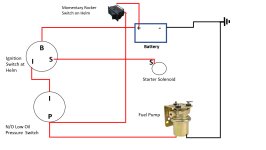
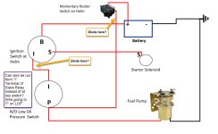
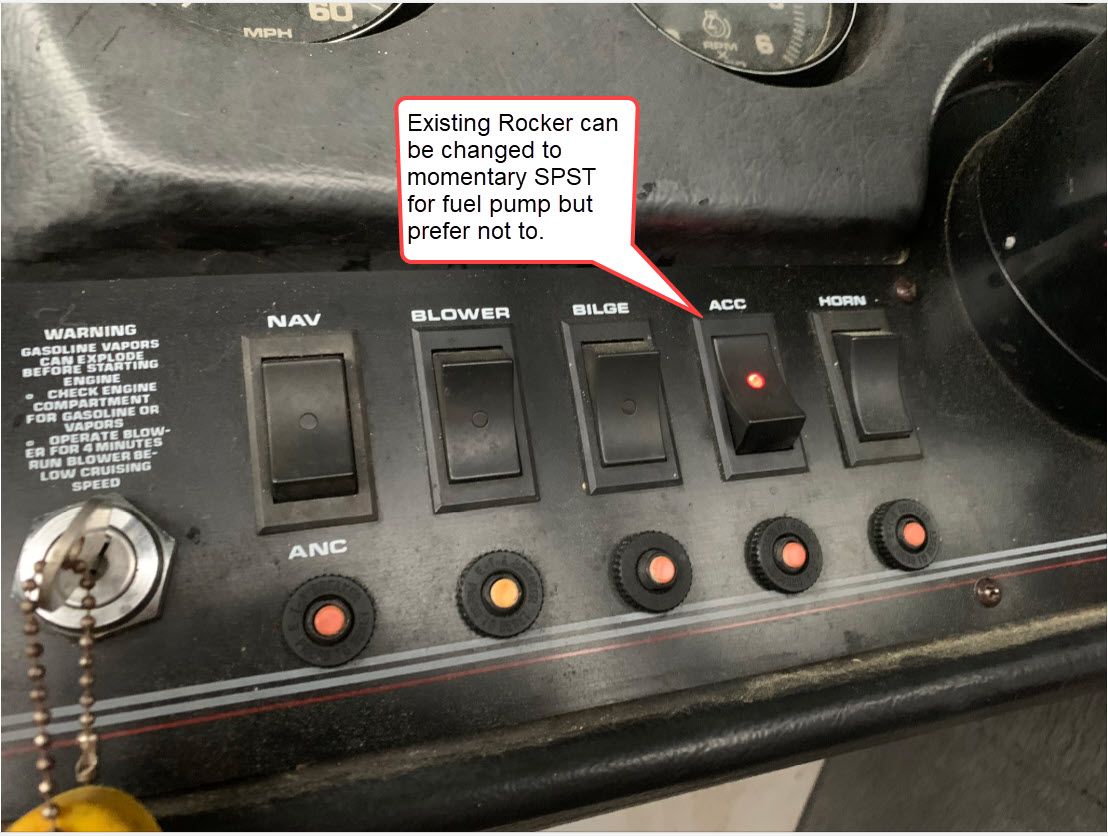
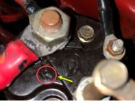
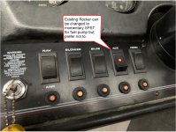
Thanks Mark but I'm confused. If you blow up the pic there is an R on the terminal. Do I still need the momentary switch? I must me missing something. It looks just like the manual. I do like the idea of having a momentary to give the carb a shot fuel so not a deal breaker, I'll just have to swap out an existing rocker which I have my radio wired to or drill a hole in the helm which I'd prefer to avoid.

Home
Outboard Motor Parts
Chrysler outboard parts Evinrude outboard parts Force outboard parts Honda outboard parts Johnson outboard parts Mariner outboard parts Mercury outboard parts Suzuki outboard parts Tohatsu outboard parts Yamaha outboard partsInboard & Sterndrive Engine Parts
Chrysler Marine inboard parts Crusader Marine parts MerCruiser sterndrive parts OMC sterndrive parts Pleasurecraft Marine parts Volvo Penta marine parts + MoreAll Engine Brands
All Manuals HomeOutboard Repair Manuals
Chrysler outboard manuals Evinrude outboard manuals Force outboard manuals Honda outboard manuals Johnson outboard manuals Mariner outboard manualsMercury outboard manuals Nissan outboard manuals Suzuki outboard manuals Tohatsu outboard manuals Yamaha outboard manuals
Inboard & Sterndrive Engine Manuals
MerCruiser sterndrive manuals OMC sterndrive manuals Volvo Penta marine engine manualsPlease Note
MarineEngine.com does not offer troubleshooting assistance or repair advice by email or by telephone.
You are invited to join our public Boat Repair Forum to seek assistance from other members.
You may also visit the Boat Motor Manuals section of our site to obtain a service manual.


")