I have a 5.7L Chevy 350 engine in boat with 1991 OMC Sterndrive King Cobra. I have fought cab for a couple years. I've had recurring issues with fouling of the spark plugs . I've recently experienced engine sputtering and back fires and very rough idle at low RPM, so I suspect my power valve may have blown. I recently cleaned the plugs and it has resolved for the moment, but I expect the issue will return. I believe my timing is good because I timed it with light last season.
I've put two partial carb kits in in two years but the carb always ends up running rich. I recently watched a you tube which alerted me that I require a special clutch screw bit to get into the secondary metering block which I have never removed. I've ordered another kit and all the supplies to tear it down further and insure I clean it more thoroughly, including carb cleaner dip and brushes. Talking to a local mechanic, he tells me that even with ethanol free fuel, I should still use stabilizer and not leave fuel in the carb (I have not been using stabilizer and not drained the carb during off season. I thought with Ethanol free fuel, I did not have to worry about varnish and gumming up my carb. I was apparently wrong.
I could install a shut off valve to the fuel inlet on the carb and burn all the fuel in the primary bowl but the mechanic tells me the secondaries only open at 2/3 throttle so even if I could isolate the fuel supply there is no way to empty the secondary bowl and metering block of full of fuel which sits in the carb. I run it several times a month in warm weather (April-October). My concern is when I put it away for the short Texas winter.
Does any one know of a way to evacuate the fuel in secondary bowl, besides taking carb off and pulling the fuel bowl off?
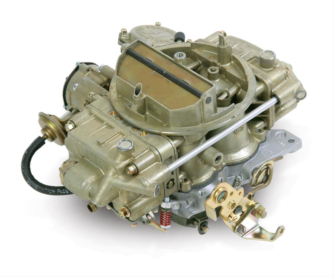
Carb is Holley 650 Model 4175 with vacuum secondaries, electric choke and a transfer tube which transfers fuel from primary bowl to secondary bowl. I tried to load pics but can't seem to successfully execute.
I've put two partial carb kits in in two years but the carb always ends up running rich. I recently watched a you tube which alerted me that I require a special clutch screw bit to get into the secondary metering block which I have never removed. I've ordered another kit and all the supplies to tear it down further and insure I clean it more thoroughly, including carb cleaner dip and brushes. Talking to a local mechanic, he tells me that even with ethanol free fuel, I should still use stabilizer and not leave fuel in the carb (I have not been using stabilizer and not drained the carb during off season. I thought with Ethanol free fuel, I did not have to worry about varnish and gumming up my carb. I was apparently wrong.
I could install a shut off valve to the fuel inlet on the carb and burn all the fuel in the primary bowl but the mechanic tells me the secondaries only open at 2/3 throttle so even if I could isolate the fuel supply there is no way to empty the secondary bowl and metering block of full of fuel which sits in the carb. I run it several times a month in warm weather (April-October). My concern is when I put it away for the short Texas winter.
Does any one know of a way to evacuate the fuel in secondary bowl, besides taking carb off and pulling the fuel bowl off?
Carb is Holley 650 Model 4175 with vacuum secondaries, electric choke and a transfer tube which transfers fuel from primary bowl to secondary bowl. I tried to load pics but can't seem to successfully execute.