Aaronfromnz
New member
when fitting the 6 bolts that clamp he sealing ring to the gimble housing do I need to seal them or put o-rings on them?
MarineEngine.com does not offer troubleshooting assistance or repair advice by email or by telephone.
You are invited to join our public Boat Repair Forum to seek assistance from other members.
You may also visit the Boat Motor Manuals section of our site to obtain a service manual.
First of all, these are a galvanized “Tap” bolt...... (i.e., threaded the full length).
No O-rings required.
To avoid future thread corrosion, coat the threads with a sealant. Quicksilver “Perfect Seal” works well.
Tighten evenly and in somewhat of a sequence.
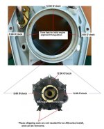
The inner rubber cushion ring provides the water seal, and should be new.
If you are installing a different engine, be sure to go through the triangulation process for the “one-time” initial Engine/flywheel cover alignment.
This would be a great time to replace the PDS bearings.
By the way, your drive is an AQ series that incorporates main suspension fork/pivot tube geometry...... i.e., no Gimbal system!
.
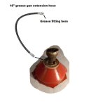
Not to hijack this thread, but how do you know when enough grease has been pumped into the PDS bearing lube port on the flywheel cover?

Thank you Rick!