Logo

Voltage spikes on Mariner 115 Hk -93

Magols

New member
Hi!

I have a Mariner 115 Hk -93. This summer 2 problem has revealed. 1) DC voltage increased with increased RPM and 2) Short and high voltage spikes noticed (the DVM suddenly and intermittent lost reading showing just OL. for a short time and the coming back to normal reading) on both DC (red wires to ground) as well as AC side (yellow wires feeding the rectifier/regulator) of the rectifier/regulator. The voltage spikes was verified when I connected an oscilloskop, where the voltage spakes was visibel.

1) Was solved by changing the rectifier/regulator.

2) Still remain. Have even tried to change stator without any result.

Is there any filter function on the adaptor sitting in between the switching box and the stator?

My theory is that the current switching of the ignition coils or switchbox are transferring a high voltage back to the stator and not cut away from a adaptor.

I have measured the adaptor and it shows 0 ohms between green/white to blue/white as well as white/green to blue. All other measurements combination on the adaptor terminals shows infinit resistance.


Best regards Magnus Olsson
 
Hi!

Both the rectifier/regulator (194-5279 CDI replacement) as well as the stator (398-832075 A3 OEM part in carton) where new parts.
 
What is the peak voltage reading you are getting? Voltage will increase as RPMs do just depends on how much. Are you having running problems with the motor? You might be looking for problems that are not there. If you had voltage going back to the stator it would have a life expectancy of minutes.
 
Last edited:
Good ideas Mr. Scott. All can add is to try a different battery and double check all connections as well as grounds. Make sure of good continuity from powerhead to cowling. Check all connections within control and ignition switch, also ammeter, of course. Ammeters can cause symptoms like this too. Try jumping the ammeter, see if you get a correction.
 
Last edited:
Hi and thanks for your response!

Motor is running normal.

Just to diffentiate between the 2 diffrent problem I have had which I think can easily can be mixed up.

1. My first problem: the DC voltage increased up to app. 18 V at high RPM:s, well above the regulator voltage which is app.14.4 V.

Solution for 1 above. I change of regulator/rectifier and now the voltage now reaches the regulator voltage app. 14.4 V so that is fine.

2. [FONT=Verdana,Arial,Tahoma,Calibri,Geneva,sans-serif]My second problem which is more difficult to understand is related to a short voltage spikes approximate 5 micro second in time and have an amplitude of +-20 V.[/FONT]
[FONT=Verdana,Arial,Tahoma,Calibri,Geneva,sans-serif]This voltage spike is superimposed with the correct DC voltage of 14.4 V and only possible to be detected by an oscilloscope [FONT=Verdana,Arial,Tahoma,Calibri,Geneva,sans-serif](on the DVM the problem only is shown as short misreading like OL and then coming back to correct reading. Earlier the reading have been steady without any OL indication).[/FONT][/FONT]

[FONT=Verdana,Arial,Tahoma,Calibri,Geneva,sans-serif]This voltage spike is visible also on the AC voltage side feeding the regulator/rectifier (but of course now it is AC voltage not DC). [FONT=Verdana,Arial,Tahoma,Calibri,Geneva,sans-serif]Even when I measured between the yellow terminals from the stator without the regulator rectifier connected.[/FONT][/FONT] [FONT=Verdana,Arial,Tahoma,Calibri,Geneva,sans-serif]Based on this measurement I tried to change the stator but problem didn't disappear. This is the reson way I now I'm focusing on that the course of the voltage spike has its origin before the stator.

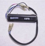
Do you know the function of the adaptor 834949A 4 sitting between the stator and switchbox?[/FONT]
 
Mr. Scott, I think you scared him away. What I think is voltage fluctuation is normal, but excessive will shorten component life. I tolerate some but they can be regulated safely by a battery, or in worst case by a capacitor.
 
Voltage fluctuations are absolutely normal. Easiest way to prove it is to watch the headlight of an older carbed snowmobile. It flickers and everyone of those flickers is a voltage fluctuation. How many times have you hooked an outboard up to an oscilloscope? I can find voltage fluctuations on a car alternator if I look hard enough. I told him twice he was looking for problems that aren't there. Voltage regulators go out that is a fact of life. His motor has a regulated system that Not my fault he got the answer he did not want. Maybe someone else can give him a hug. (tim?)

PS when was the last time you hooked an outboard up to an oscilloscope? and if you read the first post closely he is only testing the charging coils.
 
Last edited:
Amen, Mr. Scott......your "preachin' to the choir". Your rough, but correct. Now if this snow would only quit, I can get to work. Oops, how did that happen?
 

Attachments

  • IMG_20191127_134747036_compress3.jpg
    IMG_20191127_134747036_compress3.jpg
    77.9 KB · Views: 34
Stator Charging Coils Placing a permanent magnet within a ring of conductors, and rotating the magnet induces a current in the conductor (stator coil). As the North Pole is moved past a conductor coil, current will be induced in one direction through the conductor. As the South Pole moves past the conductor, the opposite magnetic field causes current to be induced in the opposite direction. You will see a small spike in the AC curve as the magnets swap poles...
 
Hi! Thanks for your answers but I still didn't [FONT=Verdana,Arial,Tahoma,Calibri,Geneva,sans-serif]receive any answer on the question.[/FONT]

Do anyone know the function of the adaptor 834949A 4 sitting between the stator and switchbox?
 
No, the adaptor is a separate component mounted from fabric. It is sitting between the stator and the switching. The OEM number is 834939A 4, see below picture. Again do anyone know the function of the adaptor (ie. it is any filter function like clamping circuit removing high voltage) or how to find a circuit diagram of the component?
Adaptor 834949A 4.JPG
 
[FONT=Verdana,Arial,Tahoma,Calibri,Geneva,sans-serif]Red stators require an adapter module that gets connected between the stator and switch box. Without the adapter module, the voltage supplied by the stator would exceed the voltage capability of the switch box. It works similar to a regulator as it tricks the switchboxes internal rectifier into thinking its on the low speed side all the time.[/FONT]
 
Your picture reminds me of those crazy Thailanders with a giant turbo diesel on a stick mounted on a surfboard flying down the canals. Check out a video or two. You think that WE are nuts? Huh! Those guys make us look like a bunch a "hullbillies." https://youtu.be/S-hrclQbFyQ
Who needs transmissions, pumps, gear cases, lower units and skegs in the water to slow you down? Make that horsepower work for you, eh? Going to ask my wife to ship me back one of them babies. You can own one of them over there for about 5 grand.
Now I got to go waste two days of my life and dig out from 2 feet of snow. Huh? Stupid.
 

Attachments

  • IMG_20191201_125543039_compress56.jpg
    IMG_20191201_125543039_compress56.jpg
    67.3 KB · Views: 30
Last edited:
Hi!

Thanks a lot for you information fuzzbullet. So I if got it right there are some internal clamping components inside the adaptor between the feeding lines to switching box reducing the AC voltage amplitude feeding the switch box when RPM rises? If so does this also mean that this function is bidirectional? That is cutting a high voltage going the other direction, which should be the high voltage being generated by the switching box caused by the on/off for the ignition coils? Or does the switchbox have a internal components for that?


My problem arose when I was forced to switch off my battery caused by a defective starter solenoid that didn't switch off when I switch off the engine. I was so surprised to hear the starter motor still running and I just turned the battery key into off position. Afterward I realized that what I created there was a very high voltage caused by the sudden current change over the coils inside starter motor. The high voltage between the battery and ground but with reversed polarity (the voltage is proportional
to u'= -L*di/dt where L is the internal inductance of the starter motor, di/dt is the derivative (current change) of the current and - showing that the voltage has a revers polarity. Normally the battery will act as a current dump load but since this was disconnected the regulator had to take the hit. But I also suspect the adaptor has been hit since it is connected to the regulator via stator).

What is your opinion, have you experience the same scenario, a starter motor still running and switched off by battery switch? Which components where destroyed then, except the regulator?
 
The adapter is behind the rectifier so therefore ac current right? It's on the spark side anyway......besides that, it's only connected with the switch box and NOT the charging system. But maybe you could replace it anyway for fun and see what happens. Unless something shorted out it should be ISOLATED from the battery, starter, rectifier, and regulator. Furthermore, if it DID short out, you would have problems with your ignition/spark system. Right? Usually when the motor is continuing to crank, the problem is in the starter switch, or solenoid, but anything that came across to provide 12 volts to the trigger side of the solenoid would be obvious. Have you had mice nesting or oxidation on wires?
 
Last edited:
I have never seen a starter cause a charging or ignition system problem as it on the battery side. Diodes inside rect/reg prevent any reverse current flow, usually when they do fail you will see a battery slowly discharge or charging system will have no output. If charging system works and ignition works and engine runs fine go boating as there isnt a problem.... Below is from Tech service manual and what wave form will resemble.....

thumbnail


4 Cylinder ADI red stator Ignition Description:
The 4 cylinder outboard ignition system is an alternator-driven (distributorless) capacitor discharge system. Major components of the ignition system are the flywheel, stator, trigger, switch box, 4 ignition coils, and spark plugs. The stator assembly is mounted stationary below the flywheel and has a single capacitor charging coil and voltage adapter. The flywheel is fitted with permanent magnets inside the outer rim. As the flywheel rotates the permanent magnets pass the capacitor charging coil. This causes the capacitor charging coil to produce AC voltage. The AC voltage then is delivered to the switch box via adapter(stabilized to X voltage no matter the RPM) where it is rectified to DC voltage(internal rectifier in switchbox) and stored in one of the 2 internal capacitors.(we are only using the low speed capacitor) The trigger assembly (also mounted under the flywheel) has 2 coils. The flywheel has a second set of magnets (located around the center hub). As the flywheel rotates the second set of magnets pass the trigger coils. This causes the trigger coils to produce a voltage pulse that is conducted to Silicon Controlled Rectifiers (SCR) inside the switch box. The SCR switch discharges the capacitor voltage into the ignition coil. Capacitor voltage is conducted to the primary side of the ignition coil. The ignition coil multiplies this voltage high enough to jump the gap at the spark plug. This sequence occurs at the correct time and firing order sequence once per engine revolution for each cylinder. Spark timing is changed (advanced/retarded) by rotating the trigger coil, which changes the trigger coil position in relation to the magnets in the center hub of the flywheel. The stop switch (or ignition switch) shorts the output of the stator to ground to stop the engine.
 
Last edited:
Thanks for your answer!

My remaining problem is actually an intermittent voltage spike (typically +-7 V and
superimposed over the real signal
) visible on both the DC side as well as the AC side of the regulator (yellow wires even when not connected to the regulator!!).

This problem (intermittent voltage spikes) as well as the none regulated DC voltage appeared after I had to switch off the battery in order to stop a running starter motor that was still running after stopping the motor caused by un hanging started solenoid.

As I earlier mentioned the first problem with the non-regulating DC voltage was solved by exchanging the regulator but the second problem still remains even though the stator has been changed. I have earlier measured on the DC level and I always been able to read a solid and stabile level, so this is new.


So my small worries here are actually if this spike can make any harm on my equipment and that is the basic driver way I’m stubborn to be able to solve also the voltage spike even though many people are reasoning like “if everything works, run the boat and be happy”J.

Since the spike has its source before the rectifier (spikes noticed on the yellow wires without rectifier connected) and the stator itself has been changed the only theoretical way is that the voltage spike has its origin earlier in the circuit or is induced into the stator wingdings.

Does the stator windings consists of 2 separate windings (coils) 1 for DC charging and 1 for charging capacitor coils?

Does the switch box have diodes parallel connected to the primary side of the ignition coils?

Do anyone know where to find a circuit diagram over the switchbox and the Adaptor?
 
You may see spikes due to regulator driving excessive voltage to ground. The stator has a battery charging winding(yellow wire) and a ignition winding (grn/grn-wht).
Here...

[FONT=Verdana,Arial,Tahoma,Calibri,Geneva,sans-serif]https://forums.iboats.com/forum/engine-repair-and-maintenance/mercury-mariner-outboards/569910-1989-mercury-4-cylinder-switchbox-question-2-wire-red-stator-or-4-wire-black-stator[/FONT]
 
Thanks a lot for the circuit diagram of the switch box.

Since the voltage spikes are measurable on the yellow wires from the stator without the regulator connected and the fact that the stator has been changed the problem with the voltage spikes as well as its origin and solution are located earlier than the stator. That’s my basic theory at the moment and the reason way my investigation are focusing on the adaptor of the switch box.

The worries I have is actually related to that equipment can be destroyed by the voltage spikes.

Do you have a circuit diagram of the adaptor as well?
 
Since you are still looking for problems that don't exist here is the solution. Never start your motor again and you will have nothing to worry about!! And get a book about how flywheel alternators work. And how sure are you that those are spikes and not drops.
 
Last edited:
Merc did not give out information other than how to test adapter. I highly doubt there is a problem and the spikes your are seeing are most likely from the N-S magnet field passing each individual bobbin on stator. I myself would put the cowling on it and go fishin....
 
Back
Top