
SwervinMervin
Member
Hi:
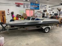
I am new to boats and outboard motors. I remember boating and skiing with my dad back in the day and I always thought boats were super cool. I don't know why it took me so long to get one of my own and go with my kids. In my mind they stopped making awesome boats in the 90's (not long after they stopped making good country music), so I really want to make this old boat run right. Late in the summer I picked up an sweet little 15.5' ski boat from the same vintage as the '73 Johnson 135hp which I purchased separately and installed on the boat.
I figure (and others whom I talk to as well) this boat should seriously rip. With a 19p prop, it gets out of the hole so-so okay and tops out at a gps'd 42 mph. I would guess that's the top speed for that prop. However, only with careful weight shifting can I barely get on plane with a 21p prop, then I can't get to any good RPM and it tops out at around 35mph. I should say I'm at 4000', but I figure the beauty glitter paint this boats' got should cancel that out as far as performance goes. Determining the RPMs has been difficult. See below.
What I know:
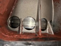
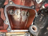
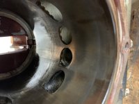
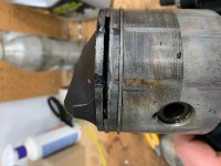
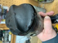
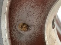
1.) Compression is 110psi on 3 cylinders, 103 or so on one of the cylinders. The side with the lower compression does seem to run a bit hotter, but not too hot: 59deg C if I remember right, 50degC on the 'good' side. I took the head off the side of concern and observed a small bit of damage on the head of the piston. Kinda looked like something solid went through the engine.
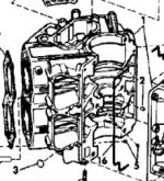
2.) I think the engine mounting is good. 1 hole up. This put the cavitation plate level with the bottom of the boat.
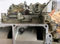
3.) Carbs are clean. I even picked up a ultrasonic cleaner for the job. Turns out I didn't need it though, they came apart nice and everything was good anyway, I figure the previous owner was in there not too long ago and did the same thing. I did notice that the sea level orifices were in there. The manual says it's good for 0-3000' and I'm at 4000'. I ordered the higher elevation orifices but have yet to install them. I think I have bigger problems.
4.) She starts and idles beauty.
5.) The rectifier tested bad. I replaced it. See below.
Here are my observations / things I don't understand / problems:
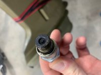
1.) All the plugs are black, greasy / kinda wet carbon caked. They are new and they are the non adjustable gap type. Maybe the higher elevation jets will help with this?
2.) This thing uses a TON of fuel. After a run on the lake I observed raw fuel sitting in the cowling near the airbox. This makes me think I have a bigger problem then just low elevation jets.
3.) The fuel issue made me wonder if I wasn't sparking right so I did a spark gap test for each of the cylinders. Set for 7/16 gap. They did good although 1 cylinder had a more yellow spark than blue.
4.) The rectifier tested bad. I replaced it later. I think it blew right away on hooking the battery back up. Again, see below.
So from the performance so far and these observation I figured that this engine can perform much better and be more reasonable in it's fuel consumption. I figured that I need a tach to be able to determine where I'm at when testing and get some answers. It only raised more questions. Here's what I did:
1.) I picked up a new Faria 0-7000 RPM tach. Hooked it up. For power to the tach and tach backlight I used keyed power from the remote. I connected the grey 'signal' wire from the remote as well. Ground to battery.
2.) The tach has a dial that can be set from 1-6. The instructions that came with the tach are undecipherable to me. Long story short is that I am unable to figure out how many poles this engine has or what setting that would equate to anyway. But: there is only 6 settings and none of them are accurate through the RPM range. I know this because I had to set the dial to 4 to have a reasonably close reading at idle ~1100RPM, I would too high for sure, but it was the closest I could get. At WOT with that 19p prop, I was getting ~6700RPM: too high, by ear I can reasonable say it wasn't crazy over-reving like that.
3.) In order to be able to get an accurate RPM reading I got a little creative. I picked up two tachs of different styles. The first an induction style tach that has a wire that wraps around the spark plug wire. By induction it counts sparks and infers RPM. I also picked up an optical tach. This thing I like. I stick a piece of reflective tape on the flywheel and the optical sensor directly measures flywheel RPM. Sweet.
4.) I was concerned about things like inductive interference with the inductive tach so I tested each spark plug wire and moved and jiggled it in every position possible. From this tach I suspect it might not be the most accurate, but I did notice it is pretty damn consistent in it's measurement. By this I mean that no matter what I did to move and screw around with an individual cylinder spark plug, it read that cylinder the same no matter what. This includes me changing out the coil on one of them.
Aside: I tested these tachs on my snowmobile. All three were pretty much bang on 1700RPM (sled tach, induction meter, and optical meter looking at primary clutch).
5.) The results: Flywheel by optical: 700 RPM. Induction measured at each cylinder: 420 RPM, 840 RPM, 900 RPM, 1050 RPM. This is a crazy result for at least two reasons. Why the inconsistency between cylinders? How can two of the cylinders be higher then the actual RPM from the optical meter ( I would say the optical meter is indisputable)?
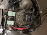
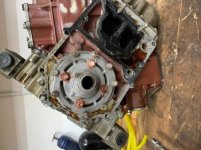
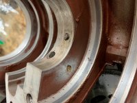
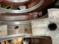
6.)I pulled the flywheel and inspected the stator and base timer. Both looked good. Oddly, I observed some of that sticky brown stator juice on the engine but the stator looked totally good. I think it might have been replaced by the original owner. I did an ohm check on the stator leads but not knowing what the reading were supposed to be all I can say is that they were some number of ohms but not shorted out between any leads (I think I'm telling the truth, as I'm going by memory, if this is critical knowledge I can pull the stator and give concrete numbers). I was also disappointed that a stator test was not laid out in the service manual. I have to say that service manual totally sucks.
7.)From the RPM results I figured that if different funny electrical things are happening between different cylinders, the power pack must be to blame. So I replaced it, I replaced the rectifier at the same time. But like I said earlier I think I blew it as soon as I hooked up the battery.
8.)With everything back together (and at the time unaware of my rectifier issue continuing) I put 'er on the muffs and repeated my RPM test. Same results. Like exact same results.
Commenting on the rectifier: I think it was on this forum that I read that a rectifier will not fix a spark problem. Period. I think I agree with that statement. Can a bad rectifier wreck a power pack or stator which in turn can cause a spark problem? I'm not so sure about that.
I realize the extreme length of this question/story. I figure more detail the better. Please let me know your thoughts.
I am new to boats and outboard motors. I remember boating and skiing with my dad back in the day and I always thought boats were super cool. I don't know why it took me so long to get one of my own and go with my kids. In my mind they stopped making awesome boats in the 90's (not long after they stopped making good country music), so I really want to make this old boat run right. Late in the summer I picked up an sweet little 15.5' ski boat from the same vintage as the '73 Johnson 135hp which I purchased separately and installed on the boat.
I figure (and others whom I talk to as well) this boat should seriously rip. With a 19p prop, it gets out of the hole so-so okay and tops out at a gps'd 42 mph. I would guess that's the top speed for that prop. However, only with careful weight shifting can I barely get on plane with a 21p prop, then I can't get to any good RPM and it tops out at around 35mph. I should say I'm at 4000', but I figure the beauty glitter paint this boats' got should cancel that out as far as performance goes. Determining the RPMs has been difficult. See below.
What I know:
1.) Compression is 110psi on 3 cylinders, 103 or so on one of the cylinders. The side with the lower compression does seem to run a bit hotter, but not too hot: 59deg C if I remember right, 50degC on the 'good' side. I took the head off the side of concern and observed a small bit of damage on the head of the piston. Kinda looked like something solid went through the engine.
2.) I think the engine mounting is good. 1 hole up. This put the cavitation plate level with the bottom of the boat.
3.) Carbs are clean. I even picked up a ultrasonic cleaner for the job. Turns out I didn't need it though, they came apart nice and everything was good anyway, I figure the previous owner was in there not too long ago and did the same thing. I did notice that the sea level orifices were in there. The manual says it's good for 0-3000' and I'm at 4000'. I ordered the higher elevation orifices but have yet to install them. I think I have bigger problems.
4.) She starts and idles beauty.
5.) The rectifier tested bad. I replaced it. See below.
Here are my observations / things I don't understand / problems:
1.) All the plugs are black, greasy / kinda wet carbon caked. They are new and they are the non adjustable gap type. Maybe the higher elevation jets will help with this?
2.) This thing uses a TON of fuel. After a run on the lake I observed raw fuel sitting in the cowling near the airbox. This makes me think I have a bigger problem then just low elevation jets.
3.) The fuel issue made me wonder if I wasn't sparking right so I did a spark gap test for each of the cylinders. Set for 7/16 gap. They did good although 1 cylinder had a more yellow spark than blue.
4.) The rectifier tested bad. I replaced it later. I think it blew right away on hooking the battery back up. Again, see below.
So from the performance so far and these observation I figured that this engine can perform much better and be more reasonable in it's fuel consumption. I figured that I need a tach to be able to determine where I'm at when testing and get some answers. It only raised more questions. Here's what I did:
1.) I picked up a new Faria 0-7000 RPM tach. Hooked it up. For power to the tach and tach backlight I used keyed power from the remote. I connected the grey 'signal' wire from the remote as well. Ground to battery.
2.) The tach has a dial that can be set from 1-6. The instructions that came with the tach are undecipherable to me. Long story short is that I am unable to figure out how many poles this engine has or what setting that would equate to anyway. But: there is only 6 settings and none of them are accurate through the RPM range. I know this because I had to set the dial to 4 to have a reasonably close reading at idle ~1100RPM, I would too high for sure, but it was the closest I could get. At WOT with that 19p prop, I was getting ~6700RPM: too high, by ear I can reasonable say it wasn't crazy over-reving like that.
3.) In order to be able to get an accurate RPM reading I got a little creative. I picked up two tachs of different styles. The first an induction style tach that has a wire that wraps around the spark plug wire. By induction it counts sparks and infers RPM. I also picked up an optical tach. This thing I like. I stick a piece of reflective tape on the flywheel and the optical sensor directly measures flywheel RPM. Sweet.
4.) I was concerned about things like inductive interference with the inductive tach so I tested each spark plug wire and moved and jiggled it in every position possible. From this tach I suspect it might not be the most accurate, but I did notice it is pretty damn consistent in it's measurement. By this I mean that no matter what I did to move and screw around with an individual cylinder spark plug, it read that cylinder the same no matter what. This includes me changing out the coil on one of them.
Aside: I tested these tachs on my snowmobile. All three were pretty much bang on 1700RPM (sled tach, induction meter, and optical meter looking at primary clutch).
5.) The results: Flywheel by optical: 700 RPM. Induction measured at each cylinder: 420 RPM, 840 RPM, 900 RPM, 1050 RPM. This is a crazy result for at least two reasons. Why the inconsistency between cylinders? How can two of the cylinders be higher then the actual RPM from the optical meter ( I would say the optical meter is indisputable)?
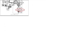
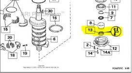
6.)I pulled the flywheel and inspected the stator and base timer. Both looked good. Oddly, I observed some of that sticky brown stator juice on the engine but the stator looked totally good. I think it might have been replaced by the original owner. I did an ohm check on the stator leads but not knowing what the reading were supposed to be all I can say is that they were some number of ohms but not shorted out between any leads (I think I'm telling the truth, as I'm going by memory, if this is critical knowledge I can pull the stator and give concrete numbers). I was also disappointed that a stator test was not laid out in the service manual. I have to say that service manual totally sucks.
7.)From the RPM results I figured that if different funny electrical things are happening between different cylinders, the power pack must be to blame. So I replaced it, I replaced the rectifier at the same time. But like I said earlier I think I blew it as soon as I hooked up the battery.
8.)With everything back together (and at the time unaware of my rectifier issue continuing) I put 'er on the muffs and repeated my RPM test. Same results. Like exact same results.
Commenting on the rectifier: I think it was on this forum that I read that a rectifier will not fix a spark problem. Period. I think I agree with that statement. Can a bad rectifier wreck a power pack or stator which in turn can cause a spark problem? I'm not so sure about that.
I realize the extreme length of this question/story. I figure more detail the better. Please let me know your thoughts.

")