Logo

1979 Mercury 9.8 timing marks (breakerless ignition)

79josh81

New member
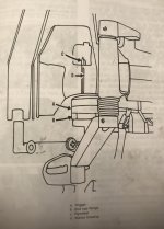
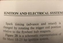
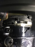
Hey everyone, new member here. I’m trying to set the correct ignition timing on a 1979 Mercury 9.8 (110). It has a breakerless ignition. I’ve been reading through the service manual I have and it’s telling me to align the “trigger assembly” timing marks with the “end cap flange” timing marks. I think I’ve identified the both the trigger and end cap under the flywheel and I see some marks. Here’s a pic of the area...A09DC7CE-144F-456F-B9E4-A4DD20FAF2E6.jpg
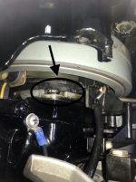
The top dark strip is the trigger and the bottom silver strip is the end cap below the trigger. The trigger has 2 lines on it and the end cap has two lines on it. The problem is I don’t know which line from the trigger to line up with the end cap. Here’s the timing lines...
6F90648A-51F2-4BCE-9EA7-1BBDC1F73FBF.jpg
As you can see in the pic, the two lines on top and bottom are spaced differently so I can’t line up both at the same time. Because of that, I’m not sure how to line these “timing marks” up like my service manual tells me to. Does anyone know where the lines are supposed to be in relation of each other?
 
It just runs rough at low idle. I still have to clean the carb and make sure the carb's idle circuit is clear so it could be that for sure but I'm just looking over everything trying to figure out how the timing marks are supposed to align. I know the timing might usually not ever need to be adjusted but I just want to check it in case the previous owner(s) adjusted anything with the timing over the years that may be wrong.
 
Last edited:
Timing's not the problem here. Mess with the carb.

Jeff

I understand it’s probably not the issue for the symptoms I have which is why I left out the symptoms of the rough idle out of my original post. I’m just interested in how these timing marks are supposed to line up just for “peace of mind” before I start taking stuff apart. The service manual says at full throttle in forward gear (with the engine off) that the marks should match up. Do you guys or anybody know what it’s supposed to look like when the timing marks are “matched up” on full throttle on this particular engine? Going through the carb and cleaning and tuning it should really only be done after you’ve verified the ignition timing is set correctly. While the timing probably is correct, I’d like to make sure if you get what I’m saying.
 
I time motors like this by the following method:

1. Remove the carb throttle cam (one slotted screw) to allow full spark advance without excessive rpm--it'll turn about 3 grand or less.

2. I use a timing light to put her right on the mark.

Jeff
 
I time motors like this by the following method:

1. Remove the carb throttle cam (one slotted screw) to allow full spark advance without excessive rpm--it'll turn about 3 grand or less.

2. I use a timing light to put her right on the mark.

Jeff


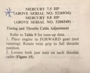
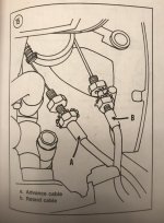
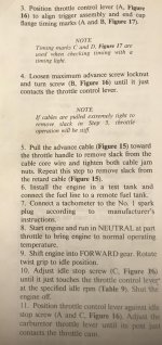
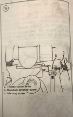
Maybe what I’m trying to do is align these marks for the throttle timing? Either way, I’m not understanding how these marks are supposed to line up. There is one solid line on the actual flywheel and also one dashed line on it and there’s one on the cowling frame to match them too but I’m looking at something else. Here’s what the manual says so maybe you guys will understand what I’m looking at better....
2CF1745D-489D-49F5-BE55-5B17CDCBC5A1.jpg
 

Attachments

  • 41C39555-35B7-4406-9521-DF7677B91801.jpg
    41C39555-35B7-4406-9521-DF7677B91801.jpg
    86.2 KB · Views: 37
  • 47DE0773-4BD3-457F-828E-C36D68C5BA62.jpg
    47DE0773-4BD3-457F-828E-C36D68C5BA62.jpg
    112.3 KB · Views: 41
  • D0370087-9F30-432F-BEFC-BBACCB1C5A27.jpg
    D0370087-9F30-432F-BEFC-BBACCB1C5A27.jpg
    93.2 KB · Views: 29
  • DA81ADF3-7B44-4226-A600-670142FFD7EC.jpg
    DA81ADF3-7B44-4226-A600-670142FFD7EC.jpg
    86 KB · Views: 31
I have a timing light and build motorcycles so I understand how to set advance, retard, TDC....etc. I’m just trying to understand where and when all of these timing marks on the trigger and end plate and then the ones on the flywheel and cowling frame are supposed to line up. Basically I have a lot of timing marks and nothing to reference to where the marks are supposed to line up. That’s the only thing I really need to know and then I can figure out the rest on my own. This is the first outboard I’ve ever worked on so I’m trying to understand the timing marks on this particular outboard.
 
There's a degree scale on one side (frame?) and a TDC mark on the flywheel. Fire it up and line 'em up! Just like bikes and cars.

Jeff
 
Perhaps crankshaft seals are leaking.----Fairly common issue.----Post compression test numbers.-----Or inspect pistons / rings via the transfer port cover.----Starboard side of the block.----Anout 5" long by 1-1/2" with 3 screws.----Replace water pump impeller before starting this motor.
 
There's a degree scale on one side (frame?) and a TDC mark on the flywheel. Fire it up and line 'em up! Just like bikes and cars.

Jeff

Theres no degree scale on this motor. There’s only the two marks on the flywheel and then one mark to line up with on the frame that goes over the flywheel.
 
I have rebuilt more than one of these wonderful motors.----Never had to worry about setting the timing.----Trounle shoot and find the reason for the rough idling !!
 
I have rebuilt more than one of these wonderful motors.----Never had to worry about setting the timing.----Trounle shoot and find the reason for the rough idling !!
Yeah I plan on doing the carb. I already have the carb kit and fuel pump kit and diaphragm. I’m just trying to understand everything on the model I have regardless of whether I’m going to adjust anything or not if you know what I mean.
 
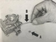
So pulled the carb today. I took out the idle mix screw and then I was supposed to take off the idle restrictor tube cap and then remove the actual idle restrictor tube. So I removed the cap and underneath was nothing. No tube no nothing. Now my service manual covers multiple years and I’m not sure of any differences there might be in carb years but do any of you guys know if I’m supposed to have the idle restrictor tube in there for sure? These service manuals are always so generic with their info if you know what I mean. Here’s a picture of the tube that’s not there from the book....it’s “B”.....
 
Back
Top