Logo

Prop for 270 outdrive? (14x19 LH)

am_dew

Advanced Contributor
I hit a stick yesterday and bent one of the fins on my 14x19 LH prop up pretty good. By chance, does anyone have a good condition 14x19 LH short hub prop they would like to get rid of? eBay seems to be fairly empty of them and a new one is about $250.

Thanks!
 
I hit a stick yesterday and bent one of the fins on my 14x19 LH prop up pretty good. By chance, does anyone have a good condition 14x19 LH short hub prop they would like to get rid of? eBay seems to be fairly empty of them and a new one is about $250.

Thanks!

I used to have that problem, so I adapted my drive to take the long hub props.
https://tinyurl.com/y3ksrgrg

But with a little work, you can get a solas to fit.
https://tinyurl.com/y68y7ye4
https://www.getaprop.com/solas-amita-3-short-hub-propeller-volvo
 
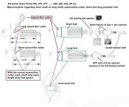
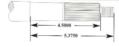
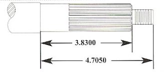
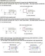
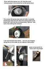
It's not uncommon to think that there is a long or short AQ series s/p prop shaft. I've even seen where some Prop Shops get this wrong!
When the correct length spacer/line cutter is used, all AQ series s/p prop shafts net the same length of splines.

The 250 and 270 drive exhaust outlet housing is not far enough AFT to allow for the larger propeller blades.
As you know, none of these shafts are internally threaded for the center locking bolt.
We don't see these threads until the 280.

Thirdly, even if you were to drill/tap the older prop shaft for the center locking bolt, you will have cut through the chrome plating, and will have exposed carbon steel to the water. If rust was to seize the bolt threads, you'll have big troubles..... especially if you were to use the locking bolt with the nylon locking-pill in it. (the bolt will snap at the pill)


Here is an old thread that may offer a better explanation.
http://www.marineengine.com/boat-fo...-series-prop-hub-length-vs-spacer-line-cutter


Prop shaft lengths explained 2 .jpg
 

Attachments

  • 280 thru SP shaft dimensions.jpg
    280 thru SP shaft dimensions.jpg
    21.6 KB · Views: 39
  • 250 thru 275 prop shaft dimensions.jpg
    250 thru 275 prop shaft dimensions.jpg
    21.2 KB · Views: 46
  • Prop shaft lengths explained.jpg
    Prop shaft lengths explained.jpg
    72.2 KB · Views: 52
If you were asking about a long hub propeller, I suppose that you could find a way to drill a safety wire hole in the spinner and also in the Prop.
 
.........................
reverse the shift and use a RH prop if necessary, volvo`s are one of the drives easily reversible
Ed, yes it is very easy to do.
However, and for reasons that I cannot quite explain, when going from a LH prop to a RH prop (on a 250, 270 or 275) the exhaust outlet trim fin/torque tab is not as effective, often causing un-correctable steer torque!

I've tried that and did not like the way the boat handled.
Did you try adjusting the trim fin/torque tab?

Hmmmm...I wonder why Jeff said it would take a little work? Jeff?
I'm not sure. I do know that the prop linked to is NOT an AQ series propeller! The AQ series did not exit the exhaust through the prop hub!


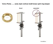
FWIW and FYI....... for those who have been running a LH prop for years and years, at some point in time you will want to examine the transmission vertical shaft "brass split ring keeper" for signs of expansion.

Am Dew prop help.jpg
 
Did you try adjusting the trim fin/torque tab?
Yes. Besides, I've got too much$ invested in LH props. Because I boat at various altitudes and get significant power loss at 4500' or higher, I use wither a 19, 17 or 15 pitch prop depending on the altitude and I keep spares for each.

FWIW and FYI....... for those who have been running a LH prop for years and years, at some point in time you will want to examine the transmission vertical shaft "brass split ring keeper" for signs of expansion.
Thank you. Do you still have the customized ones for sale? Can you point me to the part number in this link? https://tinyurl.com/y4mhpu7w
 
Last edited:
Yes. Besides, I've got too much$ invested in LH props. Because I boat at various altitudes and get significant power loss at 4500' or higher, I use wither a 19, 17 or 15 pitch prop depending on the altitude and I keep spares for each.

Thank you. Do you still have the customized ones for sale? Can you point me to the part number in this link? https://tinyurl.com/y4mhpu7w

Ricardo?
 
897313 is the brass spacer ring.... aka Split Ring keeper.

Yes, I still have quite a few of them (for the 270 - 280) in Stress Proof steel.
$45 each.
OEM brass style are over $55 these days.

If you would like to buy one, you can send a PM to me with your phone number or email address.
 
Last edited:
Thanks Ricardo...I will be in touch. I am not sure when it will happen but I need to grease my u-joint soon so I may as well replace that part while I have the transmission off.
 
am_dew said:
Hi Rick,

You may recall I inquired about the steel split ring keeper you have for sale. I am a little concerned...will I need to reshim or anything other than remove the old one and replace it with yours? If you'd rather I post this question to my thread, please let me know.

You can email me at

Thanks,
Bob

No need to re-shim anything. Watch for the existing shims when you remove the top cover. They must go back as they were.

You will need a new top cover "looped gasket" and 5 new O-rings.
dip stick
O-ring
drain plug
O-ring
hollow bolt O-ring
oil drain back tube
O-ring
large bearing O-ring


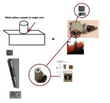
You will also need to make a vertical shaft fixture (support tool).
If you have an extra vertical shaft spline coupler, weld it to a 8" long piece of 2 X 2 X 1/4" angle iron.
Clamp the fixture in your bench vice.
Drop the transmission into the spline coupler, of which is now vertical.
This will hold the transmission while you remove the LH thread top nut.

Hmmm...I don't have a spline coupler...is there an easy workaround? Perhaps this job is getting a little too far over my head?
 
Go to your local VP shop..... they should have an extra coupler laying around.
Hah! You don't know the VP dealers around here (Sacramento). I was laughed at 15 years ago when I inquired about my then 32 year old engine and OD. I do see lots of them on eBay however.
 
Last edited:
I have quite a few AQ series parts left over from when I was doing AQ series repair.
I'll look today and see if I have any extra couplers laying around........ if so, I could send one to you.
 
I have quite a few AQ series parts left over from when I was doing AQ series repair.
I'll look today and see if I have any extra couplers laying around........ if so, I could send one to you.
Thank you! I'm trying to get a visual of this set up and how I will replace the brass spacer.

The purpose of the spare coupler clamped in a vice is to keep the transmission from turning as you loosen the LH thread top nut?

Does the vertical transmission shaft have to be completely removed from the gear box to replace the spacer?
 
......................
Thank you! I'm trying to get a visual of this set up and how I will replace the brass spacer.
Very easy once you have loosened the top nut.

The purpose of the spare coupler clamped in a vice is to keep the transmission from turning as you loosen the LH thread top nut?
When welded to the surface of the angle iron, and when then placed in a vertical position in the vice.......... Correct!

Does the vertical transmission shaft have to be completely removed from the gear box to replace the spacer?
NO!
 
Does the vertical transmission shaft have to be completely removed from the gear box to replace the spacer?
NO!

So if you don't mind me asking, how does removing the LH nut on the top of the vertical shaft allow one to remove the spacer near the bottom of that same shaft? Or will it become obvious once I remove the nut?
 
When the top nut is removed, the vertical shaft can be moved downward enough for the keeper to be moved up, which in turn releases the two split rings!
Once the two rings are removed, the keeper will slide downward and off.

If the keeper is good, the sides will be parallel to one another.
You can test/look at this by placing the keeper in a dial indicator caliper.
If the sides mate nicely to the caliper jaws, they are parallel.

If the keeper is beginning to expand, the keeper will not mate nicely into the caliper jaws (showing an angle difference) indicating that the sides are not be parallel.


By the way, I did find an extra spline coupler.
If you buy a stress proof keeper from me, I'll send it and the coupler to you.


.
 
Last edited:
These images may help explain.


brass split ring keeper good or bad.jpg

Keep in mind that the top nut is Left Hand.
When re-installing the nut, clean threads of any oil.
Use a thread locker...... Loc-tite, etc.


Volvo Penta fixture for holding transmission or lower.jpg
 
Last edited:
These images may help explain.


View attachment 20699

Keep in mind that the top nut is Left Hand.
When re-installing the nut, clean threads of any oil.
Use a thread locker...... Loc-tite, etc.


View attachment 20698

Thanks Ricardo, this is very helpful. Can you point me to where I might find larger versionds of the pics on the right side of the last collage you posted? I can't see detail when zoomed.

I will be in touch re: coupler and spacer.
 
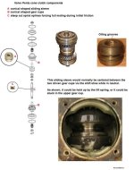
This image was put together for the purpose of explaining the cone clutch system and for a transmission that was stuck in gear.

I simply included it (small size) as to show the top nut and the lower area of the vertical shaft when the keeper and split rings are.

Once you get into it, it will all become much more clear.
 

Attachments

  • Cone clutch explained.jpg
    Cone clutch explained.jpg
    56.8 KB · Views: 33
Last edited:
Back
Top