Logo

Electrical Surge/issue Scenario

eneusiis

Regular Contributor
On my hunting boat, I have a 1998 Honda BF40 tiller. I have a Perko switch wired to a single battery, which is really just acting as a master shut off switch right now. From the Perko, it has a hot wire that powers an external fuse panel that has my lights, bildge, and graph connected to it. It also connects off to the engine for the starter.

I have two scenarios that will turn off my graph when using the engine.

1.) Upon a cold start up, it will turn off the graph if powered on before. Once warm it does not shut if off 100% of the time.

2.) Sometimes, when moving to top end speed it will shut off the graph. Either when I go from idle to max throttle or when operating at full throttle. It does not do it 100% of the time.

To me it is like my engine is drawing too much, which causes the graph to not get the required juice. The graph will turn back on if I power it up again with the engine running.

I prefer to not add a second battery, any suggestions on how to potentially solve this? I know electrical is a hard topic to digest without a graphic, I will try to make one if needed.

Thanks,

Eric
 
WOW! There could be a whole bunch of things that cause that. It's hard to diagnose without seeing it all.

Is this a new problem?

Just some top-of-mind ideas...

Make sure your alternator is putting out its rated amps.
Check all grounds for cleanliness and very good contact, especially the ground to the graph.
Try bypassing the Perko - those things do wear out and get corroded.
Make sure the wires to the fuse panel are not brittle and are at least 12 gauge. The bigger, the better - less voltage drop.
Check the fuse panel itself and make sure there is not voltage drop between there and the battery.

If push comes to shove, and you have the space, you could wire the graph display to a small 12 volt battery, like those used on riding mowers, and hook the battery to your main battery. The small battery will act like a capacitor to keep your graph display on during power fluctuation.
 
Thanks CHawk, Since the graph is wired directly to the panel, I will check the wire running from the perko to the panel and the panel itself. That seems very likely to be the number 1 suspect after reading your response with the way it is wired, I don't recall the wires be 12 gauge, I think they are smaller. I will also clean up all contacts and spray down with CRC marine corrosion blocker from the panel to the perko and all connections in between. I will try to get to it this weekend and report back.
 
As chawk_man asked, is this a new set of circumstances or are you trying to improve something that's been a pain for a while?

The graph shutting off during engine cranking may be an indication of a battery not having enough cranking amps due to undersize or age. Or, the starter may be drawing too much. When you say that things improve a bit if the engine is warm also points to capacity and/or current draw since a cold engine is typically a bit harder to turn over than at operating temperature.

One other thing about cranking to keep in mind is engine timing. An engine that is a bit out of time can make cranking harder.

Then.....you say going full throttle ALSO has the graph shutting down. Hmmmm.
That has me wondering about voltage control. As in; is the voltage regulator allowing the charging volts to spike at higher rpm? Another thing, especially with outboards, is harmonic vibrations causing a less than tight connection to separate and lose contact momentarily.

I agree with chawk_man's recommendation about larger gauge wiring being more efficient but if it worked ok before, then I suspect a problem of some sort. Although, I too agree that the action plan you have....especially the part about checking the panel out closely, is a good one.
Don't forget to remove and clean any fuses and their holders.

Standing by for your results.

Been annoying for a while. Not a new issue. I have just lived with it. I know the battery has enough CCA, it did it with my 5 year old battery and my brand new battery, both batteries are operating as designed.

I did look at the wiring that the previous owner did, although routing is all correct etc..but the wiring is suspect, it is smaller gauge and old. So, I am going to beef up the wire and see where it goes.


When it drops it at high RPM could be a vibration since it is a tin can boat, shaking the **** out of the fuse panel.

Timing was just done last year and did not change the situation, prior to timing maintenance check and new belt. Valve clearance was also performed.
 
Let us know what you find...

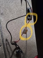
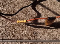
well I dig into it and I think the connection from the power terminals to the jumper to the positive and negative wires to the fuse panel is the culprit. The previous owner spliced a 25 amp in-line fuse that is a smaller gauge wire than the positive and negative. So for starts that has to change my quest is if the inline fuse is necessary. It is going to a fuse panel already which makes this seem redundant. The fuse was also mildly corroded so it has to go or change.

So so do I need the inline fuse? I have a separate battery to my electric motor with a minnkota circuit breaker so I see no purpose for this inline.
 
It's good practice to have a breaker installed on the positive side coming off the Perko to the main power line going to the console panel. The purpose of the breaker is to protect the wiring and any equipment downstream from the breaker.
 
It's good practice to have a breaker installed on the positive side coming off the Perko to the main power line going to the console panel. The purpose of the breaker is to protect the wiring and any equipment downstream from the breaker.

Okay, if that is the case, I think I will go the route of an breaker versus an inline fuse. I really like the breaker I put in on my minnkota. Any recommendations? I know the breakers run like 50 - 300 amp, is it more desired to have a 25 amp fuse so it breaks first?
 
Last edited:
If breaker installed, no need for the fuse off the Perko. BUT, all of your equipment - MAP/GPS, lights, horn, etc. - should be wired to a fused switch panel - the kind with the rocker switches and a fuse for each one. Be sure to match fuses to the load. Do not pull power off the key switch except for gauges. Bilge pump and float switch should be wired directly to the battery with a fused positive line.
 
You can find self resetting circuit breakers for 10 amp and above duty pretty easily. And I even have some in my tool box that are rated at 2.5amps.

My concern with what you have now is wire size and ampacity. A 25 amp circuit should use a 12 or 10awg size wire circuit if it is, indeed, going to carry that much current. If you use wire that is too small to carry that much current, the wire, instead of the fuse, will overheat and typically catch fire before the fuse blows if there is a short to ground.

There are a multitude of wire gauge/fuse charts for ampacity that you can download to help guide your decisions.

The other thing I see in your photos is the butt splice connectors. While they work, they don't work well and fail often from corrosion and vibration.

Correctly twisted, soldered and shrink wrapped connections will carry current efficiently and remain trouble free for the most part.

Using a clamp on type amp meter to monitor what is flowing through the circuit is also a great tool for setting things up to work properly.

You are right about having redundant fuses in a circuit. That usually only adds unnecessary connections and increased resistance. Inline fuses would only be necessary in "branched off" circuits that power smaller consumption devices. But, the base circuit must have been designed to have the additional power reserve to support the additional load.

Keep us updated on your progress please.
 
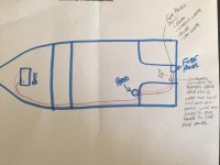
Okay here is my elementary picture for everyone. The short section between the fuse panel and the perko leads from the battery is what is the issue. The battery leads appear to be 6 Gauge wire. Where the outboard and fuse panel leads connect, today they are all stacked on a bolt and wrapped with electrical. I think my plan is as follow: 1. Install a positive and negative supply bus bar where the perko feeds it and then the outboard and the fuse panel leads can connect in a safer manner. https://smile.amazon.com/Bay-Marine...37c9578a45c&pd_rd_wg=KKikQ&ref_=pd_gw_cr_simh

2. The fuse panel wire section I will replace with 8 gauge wire to be safe and install an inline soldered joint or breaker of 25 amps on the hot lead going to the fuse panel.

https://smile.amazon.com/Circuit-Br...t+breaker&qid=1553795177&s=electronics&sr=1-2

How does that sound?


IMG_4785.jpg
 
Sounds pretty good to me. I especially like the idea of using bus bars. They are efficient and clean things up nicely.
 
Looks good. Yes on the bus bars. And do yourself a favor - tag and label every wire. I use those little round disks with string attached that you can get at most any hardware store.
 
Back
Top