Logo

1978 Johnson 55 hp 2 stroke outboard 55el78s wiring problems.

My boat has sat long enough for the engine wires to corrode. Has Sat for years. I have watched you tube, & have looked at my motor manual. I would like to find a detailed description of where all engine wires go. I have not looked at your diagrams yet.

You tube has a video that shows how to bypass the ignition. Right now, I am seeking the basic information that will to begin with some idea as to how to progress.

One video show the solenoid, but I am not exactly sure where the wires go on the terminal box.

I am just beginning to figure out the wiring.

Thank you,

Ed
 
Tomorrow I will stroll out to the shop, and see if my service manual has something I can photograph for you.
 
My boat has sat long enough for the engine wires to corrode. Has Sat for years. I have watched you tube, & have looked at my motor manual. I would like to find a detailed description of where all engine wires go. I have not looked at your diagrams yet.

You tube has a video that shows how to bypass the ignition. Right now, I am seeking the basic information that will to begin with some idea as to how to progress.

One video show the solenoid, but I am not exactly sure where the wires go on the terminal box.

I am just beginning to figure out the wiring.

Thank you,

Ed

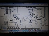
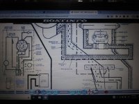
There is a manual that covers 1971- 89 ,1-60 hp engines on the boatinfo website. Appenix page A39 is the wiring diagram for your motor

Marineengine will not let me post a link but perhaps you can construct one from

http://www dot boatinfo dot no/lib/evinrude/manuals/1971-1989johnsonevinrude.html#/0

Otherwise Google will find the site easily enough

Better still buy a manual from Marineengine
 
Last edited:
Tomorrow I will stroll out to the shop, and see if my service manual has something I can photograph for you.

Thank you. I will go back over the information that I have gained, and give a more detailed explanation. I appreciate your assistance. I have never worked on a outboard, but with the you tube video's I now have a better idea as to how to begin. Ed
 
The resources we have now, since I started outboard repairs back some 50 years ago, are astonishing. Parts are available without leaving your home, and at a better price than the dealer. I can only praise those like you that use these resources to repair their own equipment. Some you tube stuff is wrong, but most is very helpful and honestly presented. Today, there should never be heard...." I, don't know"......but instead, "I'll find it for you". Take care, Tim
 
The resources we have now, since I started outboard repairs back some 50 years ago, are astonishing. Parts are available without leaving your home, and at a better price than the dealer. I can only praise those like you that use these resources to repair their own equipment. Some you tube stuff is wrong, but most is very helpful and honestly presented. Today, there should never be heard...." I, don't know"......but instead, "I'll find it for you". Take care, Tim

I appreciate the information on the wiring. I found similar diagrams in my motor manual. The issue that I have is these diagrams are great for those with experience working on motors. I am new to this. I am looking for a more detailed diagram. One that gives something similar to a tutorial that could be used by a beginner.
The internet has much information. I have yet to find a site that gives the type of information for someone new to rewiring an outboard.t
 
Right, I can see it looks like a maze to the average individual. I was lucky, my Dad was an electrical engineer and helped me along. Do you know someone who could explain that diagram for you? You probably are going to have a hard time to find an online tutorial regarding this, but it may help if you just google up a general search on "how to read wiring schematics/diagrams." It looks like Chinese, but its really quite simple to get it figured out.
 
See it all the time ---wires and 12 volts are very confusing to some.-------Problem is you can not see electricity.----You can not see how it works.----You first have to learn about electricity.
 
Thank you for the information. I found another that your team may also have information on. www.ReadManual.com. Cost me $14.00. I am not sure how it would compare to a dealer's shop manual. I am still looking for the shop manual.

There are parts such as the rectifier that I would not not be able to point out on my motor.
I am going to ask someone. Questions that experienced mechanics know. I want to step off of the first rung on the ladder though. I am at the wiring now. We'll see how it goes. Thank you. Ed

The service manual is available from Ken Cook:

https://www.outboardbooks.com/manual/55EL78/Johnson/

You have looked at the one I mentioned earlier presumably?

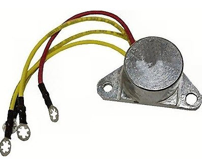
You will find the exploded engine diagrams ( click the tab at the top of this page) useful for identifying parts. Here for example is a picture of the rectifier

0581778.jpg
 
I did go that site. I went to a marine shop yesterday. Took pictures of my engine. Bad wires and all. A mechanic happened to be in parts department and showed me where the rectifier (regulator) is, and also pointed out the temperature sensor.

Helped me a lot, since I did not know.
Now, it is all about6 figuring out the wiring.

Thank you,

Ed
 
I appreciate the diagrams, and the advice.
I have gone to the web sites, and I have made copies of the diagrams.
I plan to use a pen to highlight only those lines that deal with that part of the outboard that I am interested in at the moment.

I took pictures of my motor. I showed these pictures to a mechanic, and he pointed out the rectifier and the temperature sensor

That is it for now.
I more then likely will have other question.
Appreciate the comments.

Ed
 
I appreciate the picture of the regulator / rectifier. On the diagram, between the rectifier and solenoid, there is a tachometer and a horn. I am not sure whether there is a horn on my motor.
I would like a picture of where a horn could be. My best bet may be to go back to the mechanic that pointed out where the rectifier was.

Thank you,

Ed
 
I have no idea how to look into the control box. Think I will finish fixing the wiring that I have recently learned about. The horn is going to have to be done with supervision.

Thank you,

Ed
 
I went down and bought 18 gauage wire. I need to fix the wire that goes through #2 and #5 on the terminal block. Had 12 guage, but was not sure if it would make a difference. Decided to usse 18 guage that the diagram recommends.

As soon as this gets done I will work on figuring out where the control box would be in the wiring.
Still am not sure.

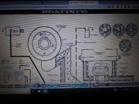
On the diagram, I see 4 circles with connectors written in the middle.
I am not sure what this is.


Ed
 
Last edited:
I bought 18 ga. wire, even though I had 12 ga. The diagram calls for 18 ga. I did not want to make a mistake by using the wrong wire. The wires going through #2 and #5 on the terminal block need repairing.

As soon as this is finished I will get to the control box.
I still am not sure where this would be.

The diagram has 4 circles with the word connectors written in the middle.
I am not sure what this is.

Thank you,

Ed
 
???-----On most boats you would sit in the drivers seat ( helm ) and look for a box with a lever within reach.----Often the hey for starting the motor is used and is part of the control box.
 
Cool. Control box information. Knowledge that those with mechanical experience take for granted.

I appreciate this forum, and You Tube.

I am not going to open up the control box.
I need to get the wiring fixed, and
I more then likely will change the impeller.
You Tube has videos on this.

One thing at a time.
T

Thank you,

Ed
 
Looking at one of the You Tube videos, I saw where the horn is.
I still want to get the wiring fixed first.

After the wiring is finished,
The plan is to look at the condition of the fluid in the lower end, and change the impeller.

I am looking at the wiring diagram for my 55 hp motor.
On this diagram there is the word Connectors.
Can anyone tell me what this means?

Ed
 
Wherever one wire connects to another... or to a terminal... or to some component... there must be a connection. If it is a wire to wire connection... there must be a connector of some kind.
 
I am going to have to look at the engine tomorrow.
Looking at the wiring diagram, I see what you are talking about.

Prior to your post, I could not see that the circles were similar to a harness.
Wires come in from the front of the boat, and go out to the motor.
Male and female parts of a wiring harness.

Its funny, I have looked at the wiring diagram at least 50 times, and did not see what you wrote about. Knowledge is definitely king.

I think that I have figured out how I am going to tackle the wiring harness.
The wires were so corroded, that I had to have new wires soldered to the short pieces that I had. We used heat shrink material after the soldering.

The heat shrink material covered the existing wire.
It is not possible to see what color the wires are.

I finally figured out today that it does not make any difference which wire is used.
On another wiring diagram, it shows that all the wires are 18 ga.
The only one that is not is the 6 ga wire that goes to the solenoid.

If my theory works, I will be able to color code the wires later.
We'll see.

Ed
 
Many years back (1968) OMC made a choice to change wiring suppliers (due to cost of course) which turned out to be a huge mistake as the insulation portion of the wires was inferior, cracked and fell away in just a couple years or so, leaving bare wires throughout their entirety.

OMC realized their error and corrected it by backtracking to a superior wiring supplier.... however it was just too late for the engines already equipped with the cut rate junk wiring.

As time went by, eventually the wiring harnesses became Non Available, and through my 30+ years of experience, I encountered a few boaters who apparently loved their 1968 engines... BUT... the wiring harnesses created a first class fire trap. The cure was time consuming and perhaps listed as expensive to some, however on three occasions what I did for the customers, as requested, follows:

A piece of 1/4" plywood, large enough to lay out the entire engine wiring harness in its original shape became my bench top.

The wiring harness was carefully removed from the engine and painstakingly laid on top of the 1/4" plywood sheet, carefully arranging it to follow the engine's curvatures and electrical taped routes.

Finishing nails were applied on both sides of the harness wires so as to keep them in place while working on restoring it. Whatever electrical tape remained, it was then removed.

Each wire was now replaced, one by one, by a same gauge identical color coded wire, with the identical terminals soldered on its ends as equipped by the factory. I always added 1" of wire to be on the safe side... better too long than to be too short!

Eventually all wires of the proper color and gauge were replaced, new terminals installed, and most important... the routing was identical as it should be (No Mickey Mouse patch work). All that was left was to apply electrical tape to keep it all together before removing it from the nail studded sheet of plywood.

Time consuming?... You betcha! Expensive?... Beats buying a new engine due to a bad wire!

Would I do it again now, at my age?.... Not on your life! :)
 
Great responses to my posts on wiring.
In the beginning I thought that it would make sense to use what is available. I have plenty of 12 gauge automotive wire laying around.

My plan is to use the automotive wire first. I want to get the wiring figured out. I will have someonewho will check my work.I don't know if I will have to redo my work numerous times or not.

As soon as the motor is running, my plan is to replace the parts used with marine wiring, and ends.

I found that 45' of automotive wire can be purchased for $7.40, and 150 terminal ends were bought, on sale, for $5.00. Marine wire will cost $13 for 35', and 3 terminal ends will cost me $5.00. There is a problem using automobile wiring.

The problem using automotive, and not marine part is durability, and fire.
How lucky do you feel. I do not want to have to repace wiring every two years or so. You all know the time frame. More important than having to do the repair, is the chance of breaking down or fire. I do not want to be far out in the delta, or the bay, and break down because I was too cheap to buy the proper wiring.

You write expensive. I get the difference in the price of the termunal ends. 3 for $5.00 or 150 of them for $5.00 (on sale). If one had a fire due to the purchase of inexpensive wire, what could that cost? It is all about what advise would we give someone else, or a customer.
 
Last edited:
Automotive wire worked for me. Frankly, in comparing automotive wire with what is on the factory equipped engines... I couldn't find a difference in quality, just problems in finding the proper color.

My mention of expense pertained to having a tech do that job as I was doing it for my customers. The hourly labor rate times 8 or 10 hours, perhaps longer = $$$ quickly.

Terminals & wire that rust in any amount of time.... Avoid, obviously.
 
Back
Top