Logo

1989 15 hp Johnson with no spark

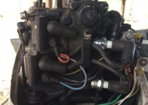
Yes, I agree with Mr. Scott. We need a proper spark test. If you hit something and key is sheared, you will still have spark, but not in time.....as previously mentioned. It will likely try to fire. You also mentioned that previous to the failure, it started better pulling over by using the recoil, because the electric starter is too slow and also drains your battery. You should be getting perhaps 100 starts on a good quality battery on this tiny starter. That is with even with no charging to the battery.
P.S. Mr. Scott, nobody agreed with me, so I came back. It wouldn't be any fun without you to disagree with me anyway.
 
0AB9C08B-02CC-468D-BC86-9280490A8712.jpg
I tried adding more pictures but this website isn’t the easiest to attach pictures. There are 3 wires coming from the dual copper coiled component.
 

Attachments

  • 781DDE13-D326-4F3D-94BB-E74CFD3E23F9.jpg
    781DDE13-D326-4F3D-94BB-E74CFD3E23F9.jpg
    47.2 KB · Views: 79
Ignition unit aka power pack? This is what I replaced after my dad and I both did research on why the motor is not getting spark. It matched the numbers on the original (I still have it). Are you saying that it doesn’t work like the original?
 
Rectifier
black to red wire, red to yellows=515
red to ground, black to red wire=1160
red to ground, black to yellows=518
reversed=0

stator
black to yellow, red to y/grey= 1
same with y/blue=1
black to yellow, red to ground =0

power pack= nothing
Couldn’t find any wires from the black box (charging coil)
 
The rectifier is for charging the 12 volt battery.-----The rectifier or the 12 volt battery are not involved with making the spark.
 
I’m sorry but I cannot determine if you are being serious or sarcastic. I tried my best to follow everything you stated from what I could find on my motor without tearing it completely down.

I was being serious. I read no feedback about the readings so I assumed that somehow I could have made my reply simpler. Keep at it... eventually it'll all come together.
 
I posted the readings I was able to get on reply #38. And posted the picture of what is under the flywheel on reply #32. The rectifier is below the terminal post. It is not allowing me to upload that picture though.
 
Keep at it... eventually it'll all come together.

Guess I will have to save my money up and pay someone to look at it and fix it, then it’ll all come together.

This is is the second time I have posted on here asking for information on fixing a motor and both are still not working.
 
Well, we tried. Perhaps we're just not capable of curing the problem.

Try another marine site forum... there's a few around. Let us know the one you pick so that we can view it. We're always looking to learn something new.
 
Hi Joe, could it be that the flywheel has lost too much magnetism and that's why he has to try to pull it over so fast? Now he can't spin it fast enough to produce effective spark? Seems the alternator is weak too. What do you think? How do you judge the magnet strength? I just use a screwdriver to see how good they pull. Then compare with a known good magnet. I feel sorry for our young boater.
Note to Partee: Sometimes those shops will " bend you over". They do the best they can but often replace parts till they get a fix.....you pay too much in the end......no pun intended, brah.
 
Last edited:
Note to Partee: Sometimes those shops will " bend you over". They do the best they can but often replace parts till they get a fix.....you pay too much in the end......no pun intended, brah.
I don’t have the cash to shell out to an actual marine shop. I’m taking it to an older gentleman who is retired and works on them.
 
I don’t have the cash to shell out to an actual marine shop. I’m taking it to an older gentleman who is retired and works on them.

Smart move... it's always the older guys who have been around the block a few times who will spot the problem, fix it, and save you a few dollars.
 
Right, ha! Thanks, Racer. This has been a very strange post. Has the guy ever given us the results of the spark test?
 
Right, ha! Thanks, Racer. This has been a very strange post. Has the guy ever given us the results of the spark test? See my post #31.
 
Joe, what do you think of my magnet idea mentioned in post #46?

That may have been possible back when I first delved into this line of work.... I remember having a portable electrical tool on a shelve just above my workbench to re-magnetize those flywheels... BUT... it was about that time that "Permanent" magnets came upon the scene.

As such (permanent magnets), I would think that problem would be pretty remote. Weird things do take place though.
 
Did I read that he replaced the spark module and gapped to .02? I really don't like the looks of his primary/exciter coil? If the flywheel was rubbing, it can fubar the magnets too. That primary or exciter coil (#36) has been toasted, in my observation here. It might show adequate resistance, but I wouldn't trust it as far as I could throw it, Joe......but who wants to listen to me anyway? A short or arc inside that exciter can toast the module, can't it? This is not for charging the battery but for exciting the module......or am I wrong? Maybe his new module is already chum. This ignition set up is not one of my favorites. What the h**# does he mean that there are no wires to check.....coming out of the "exciter" aka /charging coil / power pack? (Post # 38) Huh? That is not a power pack.....its the "exciter coil, or charging coil", it has nothing to do with the battery charging alternator.......or did I study a different book?
 
Last edited:
Did I read that he replaced the spark module and gapped to .02? I really don't like the looks of his primary/exciter coil? If the flywheel was rubbing, it can fubar the magnets too. That primary or exciter coil (#36) has been toasted, in my observation here. It might show adequate resistance, but I wouldn't trust it as far as I could throw it, Joe......but who wants to listen to me anyway? A short or arc inside that exciter can toast the module, can't it? This is not for charging the battery but for exciting the module......or am I wrong? Maybe his new module is already chum. This ignition set up is not one of my favorites. What the h**# does he mean that there are no wires to check.....coming out of the "exciter" aka /charging coil / power pack? (Post # 38) Huh? That is not a power pack.....its the "exciter coil, or charging coil", it has nothing to do with the battery charging alternator.......or did I study a different book?

I, personally, and I feel sure that many others, find your statements, replies, suggestions quite interesting, intelligent, and informative.... however, I also know the feeling and am acquainted with the effects of being ignored from time to time... and therefore I feel I can assume that, to coin a phrase "I know where you're coming from!". Don't let it get to you.

This engine, this problem, this fellow needs a bit of hands on help, someone right there by his side who can see perhaps what is not being said. Hopefully this "older Gentleman" fills the bill.
 
Although you disconnected the kill switch wires you still have to turn the key on for rope starting study the ignition switch circuit .
 
Did I read that he replaced the spark module and gapped to .02? I really don't like the looks of his primary/exciter coil? If the flywheel was rubbing, it can fubar the magnets too.

In re-reading your post reply Tim, taking it all in as the saying goes.... I agree that if the flywheel magnets were hitting any of those components attached to the armature plate... the components are toast. I couldn't comment on the flywheel magnets themselves though as they're a tough as rocks component, however I've encountered a few that were so beat up that I wouldn't reuse them.... just didn't bother testing them.
**********
The "no wires" found statement about the charge coil puzzles me..... Without that unit providing voltage to the powerpack, there would never be any spark.
**********
The statement about using a card to set the .02 gap of the spark module (powerpack?) was made in post #1. The gap of .02 I assume is meant to be .020 (20 thousands) and would pertain to the gap between the pack and the flywheel? I have heard that a business card is about that thickness and has been used by many to set points etc... so I'm not knocking that. However, how does one go about setting that flywheel/pack gap with a card with the flywheel off?

There's a special tool, a ring of sorts for setting the gap for all components located on that armature plate... and without it, it becomes a matter of using the inside bevel on top of the posts that all components sit upon to align the metal vertical portion of the components up with. I can't visualize how the card would come into play in this instance.
**********
I've looked through "Partee's" answer explanation to my post of how to test the various components via his post #38... BUT... my instructions were to him to decide whether the component(s) were good or bad via a Ohm Meter registering a "Reading" or a "No Reading" scenario. His reply, although using exact readings were confusing to me and I just couldn't get my mind wrapped around them. I had no interest in the readings themselves but rather simply "A" reading or "No" reading with the decision of the component being good or bad being his... not mine. Perhaps my instructions were as confusing to him.
**********
Engines such as this, I tend to have this wish that I could get my hands on it... not that I would go to the bother of restoring it... BUT... I'd certainly be able to diagnose the problem within the hour and to get that message across. It appears that the engine obviously exists but there seems to be an impossibility to have a meeting of the minds here.
 
Very well stated, Joe. I continue to be highly impressed with your reasoning. Either of us could probably have this repaired in short order and without even ordering any parts. I am loaded with 9.9 and 15 parts. They have been our (Dad and me)..........motor of choice through all these years at our camps up in the bush. I still own about 20 of them and half are used on a regular basis. We have 18 foot Alumarine boats with 20" transom and sometimes freight with 3 15's running side by side on one boat. Since we tear down equipment each trip, the 15's are so very easy to put back in the sheds, safe from thieves and the weather. I have seen where these coils have "spiked" and toasted p packs, even though they pass a resistance test. In this case here, it seems by the melting shown in the lads photo, that either the flywheel was rubbing, this motor was overheated, or the coil began shorting or arcing internally and got hot. As I mentioned before, these particular ignitions are not favored by me. One thing that I don't like is that the p-pack is incorporated with a coil and tucked under the flywheel where it's more likely to build heat and fail. The externally mounted packs, of course, also fail, but they are at least mounted out in the open air and catching some cooling action. Also without containing additional components they can be cooler and less problematic, not only cheaper and easier to replace.
 
Back
Top