Logo

1990 rebuilt 5.7 water in oil and timing problem

quote_icon.png
Originally Posted by RicardoMarine

Perhaps so, but have you looked to see if it's offering the correct progressive advance?

If not, the return springs may be compromised causing the BASE advance to be erratic.

but i replaced the dizzy with another unit, so wouldn't that issue be irrelevant?

My thoughts:
You have an issue that has been difficult to resolve.
Many suggestions have been made.
Nothing has offered resolve thus far.

The P of E is going to help you, and will hopefully give resolve.
In order to perform the P of E systematically and methodically, you will want to make a list of suspect areas and/or components.
You will want to stick to the list.

As you go down the list, you will want to verify the function of each suspect area and/or component, checking/testing/replacing
one item ONLY at a time.


In my opinion, the ignition distributor (even though you have this spare) should be on this list.

In order to verify (i.e., eliminate the distributor from the suspect list), you will want to have it tested by a Pro using a distributor machine.

The suggested degrees markings on the balancer would help you do an "on-engine" test (testing it yourself), however, with the other unknown potential issues, I would not suggest this............ at least not at this time!


FYI:
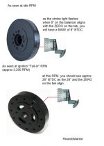
Spark advance is seen in crankshaft degrees.
BASE advance will be seen as 6* or 8* and is always prior to any centrifugal action (advance).
As the engine speed increases, so does the spark advance until the spark advance reaches what we call the "Full-In" RPM.

The distributor's mechanical advancing system will offer approx 11* of centrifugal movement (flyweight/cam advance) at the distributor only.
Since the distributor shaft rotates only once per every two crankshaft revolutions, the 11* will be multiplied Xs 2
That equals approx 22* of mechanical advance that will be seen at the crankshaft.
Now add a BASE advance of 6* or 8*, and you end up with approx 28* or 30* total (at the crankshaft) when the advancing system is Full-In!

In other words, you will/should be able to move the rotor approx 11* and then see it return CCW.


Question:
If you have this distributor in hand, and if you firmly hold and prevent the driven gear from spinning (within the housing), are you able to move the rotor CW and then see it return?
If so, does it appear to move approx 11* and back?

However, this check does not indicate that the centrifugal system is offering the correct advance curve....... hence the Sun, Allen or King distributor machine testing.


It's your call...... I'm just trying to help you resolve this issue as thoroughly and as quickly as possible.


If you systematically and methodically use the P of E, you will eventually find what is wrong with this engine.
Otherwise, I think that you'll keep spinning your wheels!


.
 
Last edited:
ricardo, i SOOOO appreciate all your input but i do not follow your process. if i take the distributor and throw it in the trash, why should i continue to test it.. if the replacement dizzy has the same results.
im just trying to understand
 
ricardo, i SOOOO appreciate all your input but i do not follow your process. if i take the distributor and throw it in the trash, why should i continue to test it.. if the replacement dizzy has the same results.
im just trying to understand

You are very welcome...... and I'll stick around if you would like me to!

Questions:
The distributor that you plan to use now...... do you know for absolute certain that it works as it should, and that it offers the correct Marine Engine Advance Curve (I.E., flyweight system, return springs, advance curve, etc)
as per your OEM specs for YOUR Engine?

If you know for certain that it does, then by all means disregard my comments, and move on to the next item!

However, if you are NOT certain, I would ask you if it is worth the risk and further time trouble-shooting?


Edit:

New thought.... although a long-shot!
Some SBC crankshaft chain sprockets
offer 3 possible indexing locations (three key-ways) in order to retard or advance the camshaft.
Normally these offer only 1 or 1-1/2 degrees of separation.
What if..... I say "IF".... this sprocket was machined incorrectly, and/or was installed incorrectly?

And again..... this would be a very long-shot.... but stranger things have happened.


.

 
Last edited:
I have just read back through the thread.

Re-Cap:


in my post #4 I said: "Somewhere, something is being over-looked."


in post #5 i have confirmed tdc with a piston stop and it lines up with the timing marks perfectly.
The PPS procedure requires the use of a degree wheel and a temporary pointer.

i used a tdc locator, https://www.amazon.com/gp/product/B0...?ie=UTF8&psc=1
i confirmed that piston tdc was in line with the harmonic balancer and pointer tdc marks
How was this done?
Did you use a degree wheel and pointer, and did you roll the crank around in both directions, allowing the PPS to stop it in either direction?
Was the pointer adjusted followed by further rotations and checking, ending up with an equal 27*, 28*, 29*, 30*, 31* or 32* degree split?


i know the truck cams have an overlap in the valves which could cause seawater to be sucked in so what to do?
Is the camshaft phased in correctly?

you answered:
i dunno THE engine was built by a rebuilder in maine who "BUILDS 30 5.7 sbc engines a week, i know what i am doing" well, maybe ....
At 30 SBC engines per week (along with their other engine work), what is the likelihood of an error having been made?
that is a fair question, in my opinion.


see my post #6 for the procedure.


your post #8
yes i basicly dismissed all those ideas about degreeing the cam and such,
To my knowledge, no one mentioned degreeing the camshaft. The mention of degree checking the cam was to explain one method of seeing if the chain and sprockets were indexed correctly.

The PPS procedure is quite different.
It is used to check the accuracy or inaccuracy of the OEM TDC markings.


Again, see my post #6 for the PPS procedure.


Was all of this understood?


given that this engine starts up on 22* advance, it may indicate that the line on the harmonic balancer may be wrong.
If so, then what you only THINK is 22*, may actually be 10* or 12*.


In post #23 I have shown you an example of an ignition curve graph. This is very close to what YOUR distributor should be giving you.
it appears as though you want to dismiss this as being part of the problem.
Solution:
...... Install a NEW distributor
...... Take yours into a shop and have it checked


In post #25 I give you a list of what I would do if this was my engine and with these problems.
I have been involved with the SBC for over 50 years.


[FONT=Tahoma, Calibri, Verdana, Geneva, sans-serif][/FONT]
 
I understand there has been a lot of info thrown out at you

you really did not answer Chris's question/statement....


Plug wire orientation, Are you 100% sure that the wires are in the correct firing order? He suggest a crossed wire perhaps. You said what type not if they were correct.

Report back with that info.

Also I agree second distributor (points) disqualifies a distributor issue. Doubt two have the same issue.

Regarding TDC and the timing chain cover mark.

There were issues back then although i have never seen it myself, There was a difference in covers that allowed the wrong TDC location. I am not sure if it was with the Vortec or prior model engines. Just some food for thought and maybe throw the question out with the engine builder or your friend


I asked if you are in Maine?
If not where?
 
Last edited:
I understand there has been a lot of info thrown out at you

you really did not answer Chris's question/statement....


Plug wire orientation, Are you 100% sure that the wires are in the correct firing order? He suggest a crossed wire perhaps. You said what type not if they were correct.

Report back with that info.

Also I agree second distributor (points) disqualifies a distributor issue. Doubt two have the same issue.

Regarding TDC and the timing chain cover mark.

There were issues back then although i have never seen it myself, There was a difference in covers that allowed the wrong TDC location. I am not sure if it was with the Vortec or prior model engines. Just some food for thought and maybe throw the question out with the engine builder or your friend


I asked if you are in Maine?
If not where?


yes the wires have been checked and triple checked, also, plug wires in the wrong firing order will not give me an issue with the timing mark unless i was on the wrong wire totally. i even moved the pick up to each plug to see if any of those locastions brought the mark to within spec

i thought about the timing cover pointer and pretty much dismissed it because the other location is straight up, not to the right and i believe it uses the 8" balancer. i am using the 6 3/4


i am in danbury ct
 
1..... yes the wires have been checked and triple checked,

2..... i thought about the timing cover pointer and pretty much dismissed it because the other location is straight up, not to the right and i believe it uses the 8" balancer. i am using the 6 3/4

1..... I think that most of us caught that earlier on.

2..... Stang, please confirm that you performed the PPS procedure as per my explanation! This is one potential variable that would be good to confirm.


.
 
Last edited:
You bought the PPS tool, correct?
Youd like to confirm TDC so that you can verify your ignition timing, correct?

You can do this without a degree wheel by using the harmonic balancer.


If interested, let me know and I’ll explain how!
 
I'm up having my coffee and did a quick search to see if I could find a decent video showing the PPS TDC procedure.

Here is one by a young man who is not using a degree wheel. He is using the outer ring of the harmonic balancer.
In lieu of a temporary wire pointer (which is used with the degree wheel), he is using the adjustable pointer on the timing chain cover.
(I doubt that you will have this style adjustable pointer)

He is not using using very many degrees of separation (i.e., a rather shallow PPS setting)
Once your PPS depth is set, be sure to lock the jam nut on it!

At around 2:30 into the video, his narration is a bit out of sync with the video..... but you will see what he means.

At 2:43 he has divided his two marker pen lines and is adjusting his pointer.
He has not mentioned that he has removed the PPS tool, of which he has done.

Once adjusted, this is his true TDC.

You may not be able to do this, unless you also have the adjustable pointer.
If not..... you can still move forward.

You will simply make a new line at the point of equal distance between your CW and CCW PPS marker pen lines.
Pay no attention to the harmonic balancer's OEM line.
Then you will compare your new "split" line with the OEM TDC markings.
If they align, you are OK.
If they do not align, then you may have found your ignition timing issue.

https://www.youtube.com/watch?v=RENhHI9n65I


NOTE:
Be very careful if using the center crankshaft bolt to rotate the crankshaft.
If you were to break this bolt, you will be pulling the engine for a machine shop bolt fragment extraction.


Here is another video showing the use of a PPS, degree wheel and temporary wire pointer.
His degree wheel is much larger than need be.

At 3:55 into the video, he removes the PPS in order to rotate the crankshaft to ZERO on his degree wheel.
At 4:30 his true TDC is found.
At this point (although not shown) he would check his findings with the OEM markings.

https://www.youtube.com/watch?v=HWZa3G6zSr4


This one is also good.
He is checking for true TDC on a small engine. Small engine or large, the principle is exactly the same.

https://www.youtube.com/watch?v=q4X03-J7SUQ


As with YouTube, more videos pop up one after the other.
Here's one showing how to check the phasing and profile of a SBC camshaft.
This is quite a bit more involved, and requires the camshaft profile information.

https://www.youtube.com/watch?v=-VwsbEg7Z4I


Stang, I am not suggesting that you check the camshaft profile...... at least not yet.
However, I am trying to stress the importance of verifying your TDC markings so that you know whether or not your ignition timing can be correct.
Until this is done, and has been removed from your P of E list, you are more or less flying blind.


.
 
Last edited:

New thought.... although a long-shot!
Some SBC crankshaft chain sprockets
offer 3 possible indexing locations (three key-ways) in order to retard or advance the camshaft.
Normally these offer only 1 or 1-1/2 degrees of separation.
What if..... I say "IF".... this sprocket was machined incorrectly, and/or was installed incorrectly?

And again..... this would be a very long-shot.... but stranger things have happened.
Stang,
You're getting great advice here. Once you've tested/corrected all that has been mentioned you should be in good shape. If you still have the problem after all that, then you need to start looking for the non-obvious possibilities. An incorrectly machined sprocket would be one of those non-obvious things.

Case in point: a friend of mine rebuilt a Jeep 4.7L V8 (SOHC). He's done about 18 of these engines plus countless others so he's extremely experienced. Once the engine was installed it would never run right. He drove himself crazy tracking/diagnosing possible causes. Nothing he tried would make it run right so he started looking at non-obvious things and tore back into the engine removing the timing chain and gears. Finally he found one of the cam gears had an improperly machined tooth that made it about 3 degrees out of spec. That flaw was just enough to alter senor locations and completely throw the ECM out of time.

So, by all means, first cover the likely culprits. If you don't find your gremlin start looking for the things that should be fine, but for some reason (example: poor machining) they are not right.
 
quote_icon.png
Originally Posted by RicardoMarine


New thought.... although a long-shot!
Some SBC crankshaft chain sprockets
offer 3 possible indexing locations (three key-ways) in order to retard or advance the camshaft.
Normally these offer only 1 or 1-1/2 degrees of separation.
What if..... I say "IF".... this sprocket was machined incorrectly, and/or was installed incorrectly?

And again..... this would be a very long-shot.... but stranger things have happened.


Stang,
You're getting great advice here. Once you've tested/corrected all that has been mentioned you should be in good shape. If you still have the problem after all that, then you need to start looking for the non-obvious possibilities. An incorrectly machined sprocket would be one of those non-obvious things.

Kevin, like said..... it may be a long shot.
And thank you for shoring up the idea.
 
Stang, I looked for a decent video this morning, but came up short. There are just too many that are not very well done. Use caution if you look at any of these!

Once you get the TDC verified, you will move on to adjusting the ignition timing.
I suggest using a standard strobe type timing light!

I put these together for you this morning.


Edit:

Regarding my second image:
In the upper example that shows a BASE of 8*, note that there is no mechanical advancing taking place during this reading.
BASE advance is a result of where the distributor housing is positioned and locked down.

In the second example, the engine speed would be increased to approx 3,200 RPM.
At this RPM reading, the distributor has added all of it's mechanical advance.
BASE would be included in this number.
 

Attachments

  • SBC harmonic balancer 1.jpg
    SBC harmonic balancer 1.jpg
    23.7 KB · Views: 143
  • SBC harmonic balancer 2 .jpg
    SBC harmonic balancer 2 .jpg
    23.3 KB · Views: 41
Last edited:
yes the wires have been checked and triple checked, also, plug wires in the wrong firing order will not give me an issue with the timing mark unless i was on the wrong wire totally. i even moved the pick up to each plug to see if any of those locastions brought the mark to within spec

i thought about the timing cover pointer and pretty much dismissed it because the other location is straight up, not to the right and i believe it uses the 8" balancer. i am using the 6 3/4


i am in danbury ct

Its not where the other pointer is on the cover.....

It has to do with the one thought to be correct not to be. It is off some degrees and could be if this is the case the cause of your timing issues.

I am not saying it is but it is another possible thing to check and confirm.

If you would like to talk send me a personal message with your phone number and i will discuss this issue with you.
 
................
Stang said:
yes the wires have been checked and triple checked, also, plug wires in the wrong firing order will not give me an issue with the timing mark unless i was on the wrong wire totally.
That is correct!
As long as plug wire #1 is connected to cylinder #1 spark plug, and you are timing from #1 wire.
The variable would be if the TDC markings are incorrect!


i even moved the pick up to each plug to see if any of those locations brought the mark to within spec


i thought about the timing cover pointer and pretty much dismissed it because the other location is straight up, not to the right and i believe it uses the 8" balancer. i am using the 6 3/4 Its not where the other pointer is on the cover.....
Again, this is why you need to perform a PPS procedure.

It has to do with the one thought to be correct not to be. It is off some degrees and could be if this is the case the cause of your timing issues.
I agree with you, and I believe that this has been discussed.
 
ok, so today i did the pps proceedure and the timing mark is less than 4* of the line on the balancer so that rules that out.
 
no not yet,it started raining but i plan on working on it tomorrow that still doesnt bring me any closer to the right timing
 
..............................
no not yet, it started raining but i plan on working on it tomorrow
Good..... you'll have two choices; a new ZERO TDC mark on the balancer, or a new ZERO mark on the tab.

that still doesnt bring me any closer to the right timing
Understood.
However, it removes this from your P of E list, in that you now know that your #1 cylinder TDC markings are fairly accurate.

1 thru 8 questions :

1..... are you using a standard strobe type timing light?
2..... are you using a digitally advancing timing light?
3..... if digitally advancing, are you using it in standard mode?
4..... if digitally advancing, are you using it in advancing mode?
5..... at what RPM are you adjusting BASE advance?
6..... as you increase RPM from idle speed, do you see additional advance occurring?

7..... are you able to get your hands on the camshaft part number that the shop used?
8..... are you able to get your hands on the camshaft profile specs?


If you find that your timing procedure was done correctly, I would suggest that next on your list will be checking the camshaft indexing or phasing to the crankshaft.


By the way..... if you take this off-forum (i.e., PMs or phone calls between you and other members) the people who are watching this thread will be taken out-of-the loop, so to speak. Plus, any errors may not be seen nor questioned/corrected!

Your call on that.


.
 
Last edited:
Stang32
check your notifications

Jack, when we start using PMs or phone calls, we prevent any on-lookers from learning what you may have shed light on.
If you have some great info for Stang, please post it so that the members can also see and read it! In other words, what you have to say may spark other thoughts, or bring up other questions.
We are all here to help Stang...... if we start taking this off-forum, Stang may miss something of importance!


.
 
Last edited:
Ricardo

F off


I will do as I please.

If you dont like it go elsewhere.

Maybe you should have suggested the same instead of spending untold hours spewing your "expertise" in type only because you are trying to make everyone THINK you are some kind of expert.

If a root cause is found after an offline discussion, this thread will get updated.
 
1 thru 8 questions :

1..... are you using a standard strobe type timing light?
yes
2..... are you using a digitally advancing timing light?
yes
3..... if digitally advancing, are you using it in standard mode? t
here is no choice , there are buttons on back that when pushed, advance / or / retard the timing
4..... if digitally advancing, are you using it in advancing mode?
no
5..... at what RPM are you adjusting BASE advance? 850
6..... as you increase RPM from idle speed, do you see additional advance occurring? yes, at 3000rpm, the advance is 29*

7..... are you able to get your hands on the camshaft part number that the shop used? not at this time
8..... are you able to get your hands on the camshaft profile specs?
n/a

 
.......
1 thru 8 questions :

1..... are you using a standard strobe type timing light?
yes
2..... are you using a digitally advancing timing light?
yes
3..... if digitally advancing, are you using it in standard mode? t
here is no choice , there are buttons on back that when pushed, advance / or / retard the timing
4..... if digitally advancing, are you using it in advancing mode?
no
5..... at what RPM are you adjusting BASE advance? 850
6..... as you increase RPM from idle speed, do you see additional advance occurring? yes, at 3000rpm, the advance is 29*

7..... are you able to get your hands on the camshaft part number that the shop used? not at this time
8..... are you able to get your hands on the camshaft profile specs?
n/a

1 & 2.... I was asking if you were using one or the other.

3..... I would suggest marking off the balancer (like suggested earlier), and using a standard strobe light, not a digitally advancing type.
Poor quality tool and/or user error could be an issue!
With a standard strobe light you will see Real Degrees/Real Time!

4..... please explain #3.

5..... ok

6..... while in standard mode???
By the way..... 29* @ 3,000 RPM is very close to what it should be!
I could elaborate on this if I knew what pistons the builder used.

7 & 8..... dang it.... too bad!


.
 
Last edited:
Stang, here's my next suggestion:

Purchase or borrow a standard ignition system timing light without the digitally advancing feature.
Purchase the correct diameter degree decal and apply it to your harmonic balancer.
Now try timing this engine in Real Degrees and Real Time, and see what you come up with.

NOTE: Since you found a 4* TDC marking error, be sure to compensate for that 4* error.
In other words, either re-mark the TDC on the balancer, or the ZERO on the tab as to correct for the error.


timing decal per diameter .jpg
 
i redid my PPS test and the timing mark is on the money. the timing mark on the balancer lines up with the pointer. the timng light is not a problem, i use it often, used it 2 days ago on a nother engine and it is working as designed. i feel the timing is not the issue.
 
hey guys i need some help, i am installing a new motor and i have it mounted on a pallet on a trailer for testing purposes, i have the manifolds risers and elbows in place. all new exhaust (sierra) and i am getting water in my oil. could the exhaust not being atached to the y pipe be sucking the water back into the cylinders? this is the 2nd time this is happened. the ist time i sent the engine back to the builder, i filled the manifolds with acetone and found no leaks, i had the intake pressure tested and no problems found.
the 2nd issue it the timing. i can not get the timing to within specs and sound right.
this rebuilt engine has a pertronix ignition in a pretrolte dist. no weights, just a shaft set up. basic.
the engine sounds the best at 22deg btdc, when i bring it to 8 deg, it runs rougher, not as smooth as 22. the vacuum gauge is very bouncy, violently bouncing from 16-22i in hg.
i have confirmed tdc with a piston stop and it lines up with the timing marks perfectly. what am i missing. i have never had an issue like this before and i am stumped
the engine has already been back to the builders and they claim there is no issue what so ever with it. so how do i ecplain the vascuum gauge dance and the timing issue?

if the water in the oil is caused by the manifold back pressure, whats the fix for that?

i know the truck cams have an overlap in the valves which could cause ewater to be sucked in so what to do?
i hope i can get some answers on this , thanks guys

I listened to your videos. I cannot explain the water in the oil if the engine, intake and exhaust pass a pressure test.

When I have an engine with an unexplained issue, I Start here.
I would pull the rocker covers and reset the rocker arms. Zero lash and then 1/2 turn. I have built many. Some like 3/4 to one turn and some like no more that 1/2. More than 1/2 and they do not run smooth.

Do it the simple way, one cylinder at a time.
 
Back
Top