Logo

Ignition Issues

Rick:

I found the old thread - see link below:

http://www.marineengine.com/boat-forum/showthread.php?380534-NEED-3-0-Mercruiser-Ignition-HELP!!!!!!

based on that, I'd say the 6ohm value is "normal"....that said, I thinkthe fix there was replacing that harness - see thread as my memory has been stressed this morning.

Agree with your test light conclusions, mostly.....would be good to verify the +12VDC feed to the coil is present when the issue occurs....but without the switching (blinking) on the cold side of the coil, it doesn't matter.....the +12VDC, from the switch is there because the light is on....

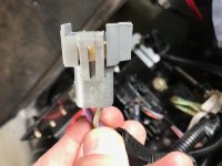
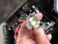
so, my current thought is where did you connect the test light to the switching signal (grey wire)?? if at the coil connector, maybe try the ICM side? also, if you have an extra set of hands, you can do the wiggle test on the ICM-coil connections while cranking. the last idea is maybe something was damaged inside the distributor during the pickup swap???

Morning Makomark, Good info on that other thread. Thanks for that. I see the OP replaced the harness and that the item is a "choke" and controls noise from the radio. Mine measures 6 ohms as well.

My test light was connected to the gray wire on the coil side. I will try the same test on the ICM side and see what I get. I have a buddy coming over tonight to help with the wiggle tests/cranking.

It's possible that something was damaged with the pickup coil swap, but I don't think so. I've worked on motors/electronics my whole life and I'm usually pretty careful when working on "sheenery". LOL
One thing I did was clean up the ground connections for the ICM to distributor using new stainless screws with liberal helping of heat sink compound.
Wait. I just thought of something. I can't recall if the paste is resistive and if I applied some around the grounds, did I lose the grounding of the ICM? I can check for continuity to be sure (ICM mount screws to ground). Probably not it, but I've seen stranger things.

Thanks as always. We'll get this figured out and hopefully, will proved others with ammo if they encounter the same.

RickR90s
 
Depends on the particular paste you have...most I've seen are insulating electrically.....and on the paste, usually less is better....

Good on your experience...guess my wording wasn't the best.....so here's the blunt version - did you check the pickup thoroughly to make sure its wasn't damaged before it was put in?sometimes, the factory isn't the gentlest and sometimes packaging is sloppy and shipped parts are always subject to abuse - especially if the 'fragile' stickers are present....

I introduced 'choke' as an electrically more accurate description for 'filter' when combined with the other data in that thread.....6 ohms is significant (too much) when you consider most ignition coils draw a few amps (on average)......so maybe the 6 ohm value is an indicator of a failed harness (bad connection at choke or burnt choke itself).....it can hurt anything to get your helper to hold a short jumper at each connector (bypassing the 'pink' wire) and see if the spark returns....
 
good morning,

The pickup coil looks un-damaged. It still measures about 800 ohms and generates up to .7vac when the cranking the engine, distributor rotating.

I spent some time last night checking continuity/resistance. I'll get my buddy tonight to help me with cranking the engine while I probe further.

Tests verified last evening:
Verify Ignition Control Module is grounded. Check. .4 ohms to engine ground via mounting screws
Verify gray wire running to tach has continuity to same wire at coil connection. Check. .6ohms
Verify gray wire is not grounded. Check. Tach side of gray wire to engine ground, infinite ohms. Coil side of gray wire to ground, infinite ohms.
Bypass the choke on the pink wire between the ICM and coil. I spliced in a wire, same gauge, giving direct shorts on both wires. Crank engine, still no spark.
Verify resistance of transmission neutral switch. Check. 7ohms in neutral. Infinite ohms in forward or reverse.
Check battery voltage at coil while cranking engine. Will complete this evening and will also verify this voltage when shifting out of neutral.
Small gray wire to tach. Where does it go? I'll verify this evening. For now, both large (coil) and small gray wires are disconnected from tach. Still no spark when engine cranks.

thanks,

RickR90s
 
neutral switch doesn't touch the ignition circuits - only the starter circuit....now, if you have a safety lanyard, that's good to check...

if battery voltage stays at the + side of the coil constantly (w/ key ON), then I'd say you've narrowed it down to the pickup coil or the module - as that's all that is involved to trigger the coil.....wow!!
 
good morning.

My boat doesn't have a safety lanyard.

Latest update. After checking all the grounds and being reasonably sure that all the wiring is good, I picked up another ICM and installed. Engine fired right up and settled into a nice idle.....for about three minutes. Then the idle raised to about 1200 and continued to rise and fall until it finally stalled.

And it's back to a no spark condition.

Trying to think of anything that could be related, last spring, I mistakenly hooked up the battery cables wrong. The battery switch was Off at the time, and turning it on, I quickly realized when I didn't hear anything "energize".

There were a couple blown fuses and after replacing, everything seemed fine and it ran great all last summer, putting on about 50 hours.

Is it possible that this issue is in the ECM? Could the ECM cause the ICM to keep failing?

Thanks,

RickR90s
 
my experience is that the GM ECU's are pretty well protected against a reverse polarity supply situation....

Once the engine is running, the ICM functions solely as an electronic switch, for firing the coil, timed by the ECU.....I cant envision a scenario where the ECU would cause the ICM to fail.....but anything is possible.

HAve you been using the same source of supply for the ICM's? In years gone by, there have been multiple aftermarket sources that had quality control issues on and off...I used to go out of my way to get the GM branded ones....but they are hard to find today.....
 
I agree Makomark. It ran fine all last summer even after the battery switching incident. But, I'm at a loss as to what could be causing the ICM to continually fail.

The first ICM was sourced at NAPA and I believe it was made in the US
The 2nd one (installed Sat afternoon) was sourced at O'Reilly's Auto Parts and says it's made in Taiwan.

I looked for authentic GM made units but agree that they're hard to find.

I am sending the ECM out for evaluation just to make sure its good.

Thanks as always,

RickR90s
 
i got a lead on a DELCO module...will send you a PM.

you may want to check with the ECU shop - they may have some ideas...
 
Just got off the phone with Bob at OBD Diagnostics and my ECM is fine. I should have it back by Sat. I'll put it all back together with yet another new ICM.

I have a 2 channel Fluke digital thermometer. I'm planning on logging temperature on the distributor plate (where the ICM is mounted) to see if there's any relationship to when the ICM fails.

FWIW, engine temperature is 160F max, according to the Faria gauge on the dash.

Thanks,

RickR90s
 
glad you got some good news.....

BTW, what's the rest of the installation in that hull? assuming single engine inboard?? inline or V drive?
 
ok...no shift interrupter to worry about...

Guess the only other parameter that may be involved would be current draw of the coil when it is running.....

Did you ever get to verify +12VDC available at the coil while running to the failure point?? I'm thinking maybe the ignition switch is aged (worn) and as the engine runs, the electrical contacts slowly increase their resistance, so the coil has to draw more and more current to make the spark....my theory is at some point, the ICM can no longer carry the current without suffering damage....
 
good afternoon makomark,

I did not verify while running I have 12vdc at the coil. my fault. I will add that test when I get the ECM back, new ICM installed. I think it would be good to have the Fluke DVM attached right at first start-up as I can compare the voltage to the temperature tests I'll run on the dist.

I intended to ohm out the ignition switch last week and doggone on it, I got distracted. I'll do that this evening.


I understand your theory. I didn't think about the DC voltage/current equation in relation to current rise in the coil. I tend to think of AC brownouts where the line voltage goes down so the current to your motor driven appliances goes up. That's why fridge's fail alot. I totally forgot about it applying to DC. Thanks
 
I wouldn't waste my time ohm-ing the switch....the DVM doesn't source enough current to trigger the issue in switch (or wire o cnecto,etc) .....that said, measuring the voltage at the coil will show you any issues in the IGN supply side....

Trying to think about all issus the MEFI manual wouldn't address because they are outside the envelope the MEFI works in.....
 
Thanks makomark for the clarification. I'll go with just measuring coil voltage as the ignition switch "appears" to be functioning just fine.
 
good afternoon,

I received my newest ICM (official GM stamp on it) this time.

Also received my checked out ECM from OBDDiagnostics today also. Good folks btw. Did everything as promised. Couldn't be happier with them calling me when promised.

Boat is running in the driveway. Per your request, makomark, the battery voltage is 13.9vdc and the pink wire on the coil is measuring 13.5vdc.

If it stalls I'll compare the two again. Crossing my fingers..............

RickR90s
 
Well, it gets more interesting. Ran absolutely beautiful in the driveway but as soon as I re-started it after launching, it acted like it was flooded.

I made it from the boat launch to my lift but the motor was constantly surging between 600-1500 rpm.

More troubleshooting yesterday and coil voltage is the same at 13.5vdc.

The only thing I added to the equation was I topped off the fuel (10 gallons) before dropping it in the water.

Observing the fuel injectors spraying into the throttle body in this current condition, the pattern changes with the rpm. I suspect that's normal. IOW, as RPM increases, the pattern gets heavier, if that makes sense.


The ECM shows no error codes with my scanner.

To re-cap, the engine will start now, but won't idle unless I give it throttle and the it surges up and down at a set throttle.

Thanks,

RickR90s
 
based on your description of the injector spray pattern, it makes sense - more rpm = more air into the engine = more fuel.

more fuel added & relocated (bounced and vibrated) the boat....and several connectors had to be reseated with the ECU reinstall...

Good that the coil voltage isn't changing.....do you know where the parameter monitoing screen is, on the scan tool? I'd suggest reading the MEFI book - ID the parameters (sensor inputs) that drive the fuel delivery, and make an assessment of them. The rationale is no code means no gross failure of any sensor detected - that doesn't mean a sensor can't be off. The MEFI book uses the ECT sensor as an example.....
 
good morning makomark,

I just have the CodeMate LED scanner and it only blinks code 12, which is normal.

I do have the MEFI book. I will investigate. I know the Rochester throttle body system has a throttle position sensor, but not sure what the other 2 connectors are.
I'll verify.
And thank you!
 
then you will have to patiently use the DVM to check the individual sensors...think the MEFI book has 'nominal values' ...the other thing to check is the reference voltages (usually +5VDC and GND) at each sensor connection....

TBI probably has TPS, IAC, and injector connections....going off memory...
 
I believe you're right. Throttle position should be mechanically connected to the throttle plate. Idle Air Control probably on there too.

There's a third connection on mine that has a vacuum hose running to the back of the throttle body. I assume it's Manifold Absolute Pressure.
 
Could be the MAP sensor, if the vacuum tube connects 'below' the throttle plates....on most engines the MAP sensor hoses goes to an intake manifold port...
 
I'm defeated. :(

Taking it to the dealer tomorrow. Thanks for all your guidance. I'm very curious to see what the issue is, because I sure can't locate it.

RickR90s
 
bummer!!

Hope you find a decent shop and they don't have too big of a backlog....

I think I finally figured it out.

Had the boat running in the driveway again and then it started sputtering. While it was doing so, something told me to wiggle the two connectors going to the coil. There's a black connector and a gray one. The gray connector has a pink wire (12vdc) and a gray wire (tachometer) lead.

Wiggling the harness at the connection to the coil restored the proper idle so I hit an "aha" moment.

Turned the engine off, and removed the connector. In the past I had pulled this connector a million times, cleaned it thoroughly, visually inspected. So I spread the male pins out just a bit and re-inserted. Started the motor and tried wiggling the connector and the motor didn't hiccup a bit. It appears that the male pins were a bit thicker when new, but now are totally compressed and can't be spread out. So for now, spreading the pins a bit and putting a very slight twist in them appears to give good contact.

"Hmm, on to something here". I then got my Fluke out and checked the pink wire connection all the way back to the relay, and while wiggling the wire, see NO change in resistance. Then did the same test with the gray tach wire. Again, NO change.

So I'm about 99.9% sure, that the issue is at the connection point to the coil. I didn't see a way to cleanly pop the male pins out of the connector to replace with new, so I ordered a new harness that I'll splice in, with soldered leads and waterproof connectors.

If anyone else has this same issue, check this connector first. If only I had checked this while the engine was running, I think I could have saved some money. I was going down the path of Ignition Control Module's failing over and over.

Hope this helps,

RickR90s
 

Attachments

  • Gray connector to Coil 1.jpeg
    Gray connector to Coil 1.jpeg
    91.8 KB · Views: 92
  • Gray connector to Coil 2.jpeg
    Gray connector to Coil 2.jpeg
    89.2 KB · Views: 91
good job on the troubleshooting...

based on memory, a weather packs terminal service kit should be adequate to liberate the pins....another item that may help is NYOGEL.....it is worth the premium in my opinion....has been good on auto and boat application, where any connector is involved.
 
I got the new harness spliced in last night (thanks makomark for the NYOGEL tip).

Interestingly, the engine still has intermittent non-starting issues if I move the connector. So it appears that the real problem is the female connectors in the coil. I don't see anyway to modify them, so I'll be sourcing a new coil.


EST coil.jpg


Back
Top