I have a 1985 Bayliner with an AQ225D. The boat has been out of the water for a couple years before I bought it. I serviced it, freshened up the tune, etc. Changed all fluids and dropped it in the water. I immediately noticed water coming into the Bilge. It is worse with the drive in the up position -
The standard 280 is lift-out only. The 280 PT (as shown in the schematic) has power trim. Be careful when using the lift-out with the std 280.
slows down when in the down position the engine does NOT have to be running - I am relatively sure that this is not an issue with a leaky freeze plug behind the flywheel.
There will be 3 Welch plugs (casting core plugs) just ahead of the flywheel. 2 for coolant passages, and 1 at the camshaft bore.
Since the engine does not need to be running in order to see the leak, it's unlikely that the welch plugs are the offenders.
If while operating the engine on the trailer, garden hose and water muffs you DO NOT see the leak, that would further confirm that it's not an issue with the welch plugs.
I ran the boat for about an hour to check for any other issues - there were none. Engine and drive are smooth.
To diagnose the water leak I found the drive (u-joint) bellows was split.
Yep...... there is your culprit!
The drive shaft bellows is a wear item and must be routinely replaced.
To extend the life of the drive shaft bellows, never store the boat the with the drive in the UP position.
Instead, store it with the drive fully DOWN and aiming straight forward.
I pulled the drive unit out to replace the bellows.
You need to remove the transmission ONLY for this work.
If you removed the entire stern drive, re-install the lower unit and Intermediate housing as a unit.
Then install the transmission last.
Much much easier this way!
From what I can see, there is no way for the water to get into the bell housing except through the seals and bearings - is this correct?
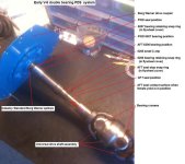
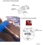
A bellows breach will allow water into the Flywheel Cover (bell housing is an automotive term) PDS area. The water will travel through the female yoke splines and into the PDS bearing area. With the PDS spinning, the water will make it's way through the bearing ball cage and eventually into the flywheel cover interior.
Can the shaft/bearing be removed/serviced from the back of the boat without having to pull the engine and remove the bell housing.
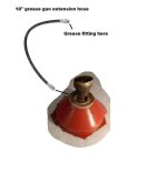
If the boat has the original red, 1 pc flywheel cover, with a grease fitting at the 12:00 O'clock position, the answer is NO!
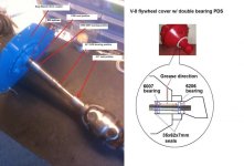
This flywheel cover arrangement uses a double bearing PDS. PDS = primary drive shaft.
The engine must be either removed, or slid forward and turned sideways, in order to gain access to the FWD PDS area.
With the 2 AFT snap rings removed, you will use a brass hammer (at the FWD side) to drive the PDS AFT and out.
The PDS will come out with the AFT bearing still attached to it.
You will then remove the FWD bearing snap ring, and then reach in from AFT and drive the FWD bearing out.
Replace the AFT bearing and re-install the PDS into the F/C.
Now install the FWD bearing, snap ring and seal.
Tip: either glue or stake this seal into place.
If you were to loose the FWD seal, no future grease will make it to/through the AFT bearing ball cage!
(see ** below)
NOTE: separate the engine from the flywheel cover, leaving the flywheel cover attached to the transom shield.
In other words, remove or slide forward/sideways the engine ONLY.
NOTE: remove the 4 lag bolts from the stringers, leaving the side engine mounts attached to the engine.
If the flywheel cover is charcoal gray and does not have a grease fitting, then yes....... the single bearing PDS can be removed without pulling the engine.
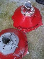
There is absolutely no rust/corrosion inside the housing so I can easily access the snap ring(s), but I am not sure that once I got the outer seal out, if the shaft can be removed.
Again, it will depend on which flywheel cover has been used.
Any insight would be very helpful
Mike, post more info and we can take it from there.