Logo

VP 280 Prop Shaft seals.

Is it possible to replace the seals and O-rings on the 280 without having to separate the housings?

If you are asking about replacing the two "back-to-back" prop shaft seals only...... yes, there is no need to remove the lower gear unit from it's above Intermediate housing.

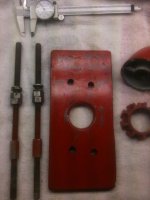
You will need to build one of my prop shaft bearing carrier puller tools as shown below.
(the other option is to use a slide hammer..... but I can't bring myself to do that against this very important bearing!)

With the two carrier cap screws removed, you will thread in the Grade #8 7/16" all-thread rod. Seat the rods gently.
Next, install the two grade #8 nuts and grade #8 washers. (I show 4, but only 2 are needed)
Next, slide the plate over the two 7/16" threaded rods until enough prop shaft is exposed to allow the spinner to be installed.

Now with the prop shaft spinner in place and up against the plate, the two "jack" nuts when turned AFT and evenly, will move the plate AFT.
As the plate is forced AFT, the spinner will pull AFT against the prop shaft.
As the prop shaft is being pulled on, it will force the carrier out of the lower gear unit housing.


The prop shaft and bearing carrier (as an assembly) will come out AFT.
Next will be removing the bearing retainer plate nuts.
Once the retainer plate is free, you can use gravity/inertia to gently slide the carrier from the large angular contact bearing.
As this point..... watch for shims, and keep them inventoried.

Once this far in, you will gently remove the old seals.
New seals are not only designated Oil/Water sides, they are also directional..... so pay close attention to the assembly instructions.

From here it's a piece of cake. :D


NOTES:

My puller is being shown while being used on an AQ series Duo Prop lower unit.
Using it on an AQ series s/p lower unit is very similar. (note the 2 different rod hole patterns)

Also, the coupling nuts shown are not necessary while removing the carrier.
The carrier must be free to slide AFT over the threaded rods.
(the coupling nuts may be used for carrier re-installation)

Occasionally we must apply heat to expand the gear case so that a stubborn carrier will come out more easily!
NO Oxy/Acet!!!!! Propane or Mapp only!


Attachments

  • Prop shaft carrier puller tool 1.jpg
    Prop shaft carrier puller tool 1.jpg
    48.9 KB · Views: 184
  • Prop shaft carrier puller tool in use .jpg
    Prop shaft carrier puller tool in use .jpg
    4.3 KB · Views: 884
Last edited:
Thanks Rick. I somewhat figured it could be accomplished based on the cross cut view in my manual. I'm not sure where the water entered, so I going to replace the drain plug O-ring and the O-ring on the one bolt on the cover plate on the upper gear housing to be safe. I'm also changing out the seal on the bearing housing for the eccentric piston as well. I replaced those (except for the seal on the eccentric piston) when I changed out the upper gear housing last year. Too, today I noticed something I never knew was on the lower housing. Below the drain screw on the lower housing, there's a hole, where water comes out when using the muffs to run the engine. I take it that it should be there.
 
...............
Thanks Rick. I somewhat figured it could be accomplished based on the cross cut view in my manual. I'm not sure where the water entered, so I going to replace the drain plug O-ring and the O-ring on the one bolt on the cover plate on the upper gear housing to be safe. I'm also changing out the seal on the bearing housing for the eccentric piston as well. I replaced those (except for the seal on the eccentric piston) when I changed out the upper gear housing last year.
If a leak is not via the prop shaft seals, the next suspect seal is the eccentric piston seal.
Keep in mind ...... although at first glance it is hard to tell by looking at it......, this seal is directional. The tiny exposed metallic area faces the inside of the unit.


Too, today I noticed something I never knew was on the lower housing. Below the drain screw on the lower housing, there's a hole, where water comes out when using the muffs to run the engine. I take it that it should be there.
Yes, it is a drain port for the lower unit seawater path cavity.
Always plug this port when using the garden hose and water muffs!
 
Rick, I'm guessing the flat stock for the puller is about 5 or 6 " H, and about 4" or so wide. But what would the spanner nut be used for? I also notice the cone in the picture too.
 
Rick, I'm guessing the flat stock for the puller is about 5 or 6 " H, and about 4" or so wide. But what would the spanner nut be used for? I also notice the cone in the picture too.

OK.... what you're calling a spanner nut is used on the Duo Prop FWD prop shaft. The AFT duo prop propeller uses a spinner..... but we don't use that for this puller tool.
The s/p spinner is used on the 250, 270, 275, 280, 285, 290 etc style drive...... as per what you have!

Notice that I have two different bolt patterns drilled in the 1/2" steel plate for the threaded rods.
This allows the tool to work for both the s/p carrier cap screw spread, and DP carrier cap screw spread. (spread = center-to-center dimension)


The large center bore allows for both the smaller s/p prop shaft and the larger FWD prop shaft of the Duo Prop to pass through it.
Both the FWD Duo Prop nut and the s/p spinner will be stopped by the plate.
Either nut or spinner is gently touching the plate.
The pulling pressure is accomplished via the two threaded rod jack nuts, and is why these must be grade #8 and lubricated.

For your 280, you will install the two threaded rods into the threaded holes where the two cap screws have been removed.
Now slide the plate over the rods.
Install the spinner onto the prop shaft threads.
Turn the jack nuts away from the lower gear unit, and turn them evenly so that they push the plate away from the lower gear unit.
As the plate is "jacked" away from the lower gear unit, the force against the spinner will start to pull on the prop shaft, of which in turn pulls the carrier from the gear unit housing.

Don't worry...... you are not the first person to not quite understand how it works.
Just do it....... and it will all make sense! :D


By the way...... one person that used my design failed to use grade #8 rods and nuts.
:mad:
His rods bent..... so off he was to purchase grade #8 .
:eek:


.
 
Last edited:
Hello Rick. I've accomplished removing the prop shaft and replaced the two back to back seals along with the O-rings. I've cleaned up everything and seem to be having a bit of trouble installing the unit back into the housing. It stops with about 1/2" or so from being flush with lower gear housing. Is there something I'm missing when installing the prop shaft assembly? Too, once I get the outdrive back together, I'm thinking I will need to conduct a vac/leak test to insure there is no other problem elsewhere.
 
I prefer to use Quicksilver “Perfect Seal” for the new seals.
I also use it for the two carrier O-rings. It helps seal and it lubricates during assembly.

Your drive and driven gear hypoid gear teeth may not be meshing, and may explain why you are having trouble with that last 1/2”!
Back the carrier out a bit, rotate one gear, start going back in...... and keep checking to see if you can feel lots of clearance between the two gears.
As he carrier is being pulled in, the clearance will close down to it’s eventual correct tolerance.


.
 
Last edited:
Hi Rick,

I am in the market for a solid 280 outdrive. The existing one on my 1979 Fiberform is a DP serial Number 287 891B.

Any chance you have a spare?

Boatgator
 
Back
Top