Logo

73 thunderbolt 650 brown wire

Hi all. I have a 73 Mercury thunderbolt 650. The engine cranks but won't start. When cranking the engine remotely with key on and plugs out I have a very strong spark from each plug wire separately (cranks well with key too).I've gone through the carbs and all seems fine. I do have a kill switch that feeds ground or absence of ground to the brown wire attached to the switch box. In the spark test above, I had strong spark with the(brand new) kill switch in either mode which puzzles me.. I have also added mixed fuel to each cylinder and the best I get is an occasional pop, which has the sound of the timing being way off and a puff of smoke from the prop. However, the timing appears to right. I carefully soldered in a new ignition switch and I have continuity everywhere I'm supposed to have it. I'm a master certified car mechanic but not a 2 stroke genius at all. I'm frustrated and stumped. I've done every electrical test I could think of and read about and what I'm finding seems to be ok although I don't have a dva to do it correctly. Any help, suggestion, question or guidance would be greatly appreciated. Thanks
 
IF that is a battery ignition motor, one brown wire (there are two) goes to the tach. The other brown wire on the other side of the switch box goes to the distributor.

Jeff
 
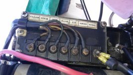
boat swx box (800x450).jpg Thanks for the quick response. I wanted to upload a switch box pic to further explain. The blue wires on the right side of pic go to the coil and are ok. The brown wire to the left is the one I have question about. It is the tach wire and it goes to the kill switch only. I believe this is a battery ignition, I do know it's cdi.
I Thought I read somewhere about attempting to start the engine with the brown wire disconnected but I don't remember the details and I prefer not to fry the switchbox by doing a test wrong. Please ask any question(s) you may have, I can use all the help I can get. Thanks Jeff.
 
Has the flywheel got the eight bolts in the middle by any chance? If it does there is a possibility it was removed by removing these bolts and not returned to the correct position. Brown is tach and shouldn't be anywhere near the killswitch.It runs through to the front of the controls. Here's a link to your wiring http://www.maxrules.com/oldmercs/Wiring/1966ona/29.jpg
 
Last edited:
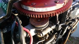
Thanks for the response. My understanding of the add-on kill switch wiring was to ground or remove ground to the tach wire to kill the ignition. Be that right or wrong, until I figure this thing out, the kill switch will remain disconnected. Yes, I do have the 8 bolts holding the flywheel down. The tape on the flywheel is very ambiguous but when #1 is at tdc and the two distributer marks line up, the tape sort of indicates it's right but I'm not sure. I've read that this engine was supposed to have an indicator that is either fixed or removable but either way I don't have it. timing pic (1024x576).jpg This pic shows the how the flywheel is presently aligned. I couldn't find a picture anywhere showing what I should see if it is correct or not. If it has a specific timing or position and it is off, can I assume the engine won't start or runs bad? Do you have an idea for a make shift timing indicator? I really appreciate your time and info. Please ask any question you may have. Mike
 
Don't make no difference how flywheel is bolted on other than to align timing decals...wont effect running. The brown wire is tach only and kill switch should not be attached to it. Kill wires attach to top terminal and engine ground.Check that spark will jump a 1/2 air gap as a weak stator will not produce a good spark under cylinder compression(pressure prevents spark)
 
Figured it out: That's a battery ignition 3 cylinder. As stated above, it will run with the flywheel in any position since the timing is done with the center hub, which goes on the shaft one way only. That said, the markings on the flywheel will be correct ONLY if IT is bolted to the center hub the right way, and it can be done 8 different ways (and it's kinda hard to time it with it off!)

Find the TDC mark on the 'wheel. Remove the top plug and stick a Phillips screw driver in the hole. Rotate the flywheel until the piston is at top dead center and see where the mark lines up. If it's off a mile, remove the 8 bolts and rotate the 'wheel about the hub until it does.

Jeff
 
Thanks to everybody for your time and expertise. I still haven't located the cause of my problem but will update if I ever find it.
That being said. I submit for you approval, a you tube video I created to show testing trigger and switchbox simultaneously.
If this was a car, I would know this test would be valid but on an outboard, not so much. Your opinions please. Thanks.
The name of the video is "1973 mercury thunderbolt 650 trigger"
 
Found problem, runs well. The timing belt jumped 2 teeth. No clear information on mechanical line up other than with the flywheel in place correctly. I found the problem by observing the position of rotor in relation to the number one contact in cap. I advanced belt one notch at a time until the engine started.
Is there a definitive mark on the crankshaft that indicates tdc?
Thank you to everybody who offered help and advice.
 
Not on the crank,but with the flywheel in belt position,the mark, the wee nub and an arrow on the pully which line up with the indicator line on the flywheel.
 
Last edited:
Its like timing a crank and cam you draw a line center of the flywheel and distributor and line up the marks i believe maxrules has instructions in their old mercs section it also shows you how to adjust the throttle pickup and max spark advance.
 
Back
Top