Logo

Thru Hull Exhaust. Do it? Don't do it? Opinions?

The critical dimension, no matter how you measure it ( the Merc manual just shows a convenient way to measure it referenced to the top of the gunwales, a spot that can be referenced accurately from both inside and outside the boat) is that the top of the elbows should be at least 13 inches above the water line. This number is totally determined by the layout of the engine. Normally Volvo 200 series drives sit such that the top of the drive case is just above the laden water line and the height of the elbows is set by the layout of the engine. That said, it is unlikely that your elbows are 18" above the water line unless there is a spacer under the elbows on the manifold. Measure waterline to highest point on transom, and from the highest point of the transom back down to the elbow.

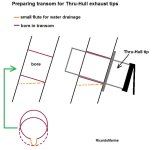
Exit point on transom... You want it such that there is at least a 1" per ft "downhill", more if possible. Most hulls nose down when the throttle is cut suddenly and you don't want the water in the exhaust line to run "down hill" back into the engine under that circumstance.
 
Last edited:
Hmmmm. Well, I've still got my waterline marks from last year because I didn't wash it down before I put it away. I've also looked back at a lot of photos. My waterline is pretty much dead in the middle of the transom shield. From that point to the bottom of the swim platform is 15". The platform itself is 3" thick. The TOP of the elbows is almost exactly level with the top of the swim platform. So top of elbow is 18" above the waterline.

If I run hose from my existing elbow to the back of the transom, I would use a 18" hose. From the end of the elbow to the start of muffler, would have about a foot of hose to get some flex out of. I have plenty of room on the transom itself to make a 1.5" to 2" drop and clear all the junk below.

I'll definitely be using a tip that has a internal flapper. I would do that no matter how high I was able to mount them.
 
If I chose to try to remove the "Y Pipe" and put a delete plate over the opening, does the motor have to be pulled? If so, I will probably pass on that idea, and just cap off the tops. Any thoughts?
 
I kind of figured that would be the response. I guess I could pull and discard the bellows, cap it there using 2 clamps, and then for extra measure, cap the tops of the Y also.
 
I kind of figured that would be the response. I guess I could pull and discard the bellows, cap it there using 2 clamps, and then for extra measure, cap the tops of the Y also.

.... I took it a step further ( didn't like the thiness of caps all that much) and found "expandable plugs" that fit, i.e. "pool" plugs with wingnuts. I coated the exposed metal parts as well with lifecalk.
 
Small update. Have everything mapped out on the inside. Moved all existing electrical runs that were in the way, out of the way. In the 12.5 inches of hose from where the water exists the elbow to the transom I have a healthy 4" drop. Well beyond recommended 1/2" drop per ft. And right at the minimum recommended overall drop.

Bottom of exhaust will be 6" off the water. If I add that to my 4" drop, that's 10" and that's pretty flush with the bottom of my elbow which is 8" tall. So my estimation of 18" above waterline to the top of the elbow earlier appears to have been correct.

Will triple check everything again tonight, and drill and install tomorrow.
 
Last edited:
Chris, I think that Bob is suggesting that the raw/exposed transom core material (the material that is now exposed from the hole-saw cutting process) needs to be protected!

Keep in mind that your structural transom angles rearward.
This means that the inside of the perpendicular hole cut is now at a higher elevation than that of the outside hole cut.
In other words...... it will have now become a small reservoir for potential moisture to collect in.

If you were to cut a down-angle "flute" from the inside into the lower-most portion of the outside hole, and then encapsulate the exposed core material with epoxy or ?????, you will protect the material from moisture damage.

If left unattended, moisture can do damage at areas that are further from the actual exhaust tip areas!

(my drawing is rather crude and doesn't do a very good job of explaining)
 

Attachments

  • thru hull exhaust outlet bore.jpg
    thru hull exhaust outlet bore.jpg
    48.2 KB · Views: 64
Great stuff guys. Thanks for the advice and taking the time to make up a sketch.

One other question. I have a plug and a cap for the main exhaust port that the bellows was attached to. Do I need to plug the two smaller holes on the bottom of the shield that the water used to come out of? I'm assuming yes. Also, what do you use to cap the top of the "Y" pipe. Both of those are oblong and not round at all. Thanks!
 
I cut the "Y's" off about 4" above the entry point to the transom shield. At that point, they are round and a standard "pool" plug fits per my previous post. Re: bypass holes, They're small, I just plugged them with LifeCalk after cleaning out the crap in the bores. A 0.45cal brass brush works fine. If you don't have one available, most sporting goods stores sell them as a separate item. A small vise grip should hold the end well enough to do the job.
 
.........................
Great stuff guys. Thanks for the advice and taking the time to make up a sketch.
You are welcome!

One other question. I have a plug and a cap for the main exhaust port that the bellows was attached to.
You are talking about the "exhaust bellows".... correct?

Do I need to plug the two smaller holes on the bottom of the shield that the water used to come out of?
The two smaller holes are for "low RPM exhaust pressure" relief.
These ports lead into the main exhaust chamber just upstream from the exhaust bellows attachment point.
In other words...... if you were to cap off the bellows port only....... your Y-pipe system would still be exposed to the seawater.

Take a look here....... you will see that all of the low pressure exhaust relief ports lead into the main chamber.
https://www.google.com/search?q=vol...16_ZAhVWz2MKHfJZAhEQ_AUICygC&biw=1600&bih=742


Also, what do you use to cap the top of the "Y" pipe. Both of those are oblong and not round at all.
I would slide the Engine forward as to create enough room to remove the Y-pipe.
Then I'd install a more proper plate that would enclose the transom shield's exhaust Y-pipe port
.
 
Also, what do you use to cap the top of the "Y" pipe. Both of those are oblong and not round at all.
I would slide the Engine forward as to create enough room to remove the Y-pipe.
Then I'd install a more proper plate that would enclose the transom shield's exhaust Y-pipe port.

Ayuh,.... Ditto This, ^^^....

If ya properly cap it off inside the hull,....
There's absolutely No reason to plug Anything outside the transom,.....

If ya plug the transom exhaust port, 'n the idle relief ports, yer creatin' a cavity that'll fill with water eventually, which'll freeze, 'n destroy the transom housin',....
 
Hi guys. I got her all drilled out and hooked up. Again, thanks to all for all the pointers, tips, tricks and advice!! I could never do these types of projects without this awesome community!!

I'll get to all the Y Pipe stuff here in few weeks, still a bit of time left before the season. A bit out of time this weekend. Here's a short video of the final result.

https://youtu.be/V1nKHkiUUlU
 
One thing I should probably point out for future readers considering this is the odd 3 5/8" O.D. of the exhaust elbows. This dimension is really not ideal as most exhaust pieces are 3 1/2" or 4". I didn't trust a 3 1/2" I.D. hose to fit well over the 3 5/8" elbow, so I went up to 4" after I found these reducing sleeves. Although 3 5/8 also was not available, I used the 4" to 3 1/2" and put the dremel to them for a few minutes and got the 3 5/8" dimension I needed. There may be other solutions out there, but this one worked well for me.

Sleeve.jpg
 
One thing I should probably point out for future readers considering this is the odd 3 5/8" O.D. of the exhaust elbows. This dimension is really not ideal as most exhaust pieces are 3 1/2" or 4". I didn't trust a 3 1/2" I.D. hose to fit well over the 3 5/8" elbow, so I went up to 4" after I found these reducing sleeves. Although 3 5/8 also was not available, I used the 4" to 3 1/2" and put the dremel to them for a few minutes and got the 3 5/8" dimension I needed. There may be other solutions out there, but this one worked well for me.

View attachment 17140

Chris, the AQ series systems often used the 95mm soft wall exhaust hose to join the Elbows to the Y-pipe inlet areas.
The 95mm is a rather unique size in terms of industry standard.
In most cases, it requires a special order.


.
 
Just one more update for posterity in case anyone decides to do this in the future. They can certainly do what I did...or not!!! ;-)

As for the Y pipe, I filled the entire lower section with the Loc-Tite brand of expanding closed cell foam. I did this in the main opening and the 2 relief ports. The main opening then got the rubber expanding pool plug and the PVC pipe cap. The relief ports then got epoxy filled at the openings, sanded and then painted, as if they were never there. I don't think there is a chance in heck that I will ever see any water in there. At some point (hopefully not during my ownership) the motor may need pulled, and at that time I would delete the Y pipe and put on a plate. But for now I should be good.

20180312_193758.jpg
 
Back
Top