Logo

Penta tilt stuck

805HD

Regular Contributor
Trying to get my friends boat ready for the summer, he’s got the penta 280 outdrive, when I flip the switch to raise the drive the “tilt rod” in the outdrive only comes out about half a inch then automatically goes back up inside the drive. I hear the relay click and all wires/ connections look good and clean.

any ideas? Place to start?

after working on this thing I REALLY LOVE my mercruiser 🙂
 
1) Did this ever work correctly for your friend?
2) Check the microswitch that sticks its plunger into the end of the housing that the lead screw runs in. Sounds like it's miswired or broken.

re: "....after working on this thing I REALLY LOVE my mercruiser .." Actually Volvos are simpler, more elegant and less "rube goldberg" than MERCs, especially the shift mechanism. "more elegant" is engineeringese for... "a small number of parts used in non obvious ways".
 
The micro switch (depressed by the vice rod during retraction only) opens the Negative circuit to prevent the worm drive form reaching its limit during retraction (drive down).

DO NOT operate the electric motor without the micro switch and cover in place!


As for the issue you are having, we need more info.


.
 
1) Did this ever work correctly for your friend?
2) Check the microswitch that sticks its plunger into the end of the housing that the lead screw runs in. Sounds like it's miswired or broken.

1. Yes it has worked for sometime now but, the boat did take on some water a while back which killed some of his wiring. I’ve been cutting wires back to clean and reconnecting them.

2. I took a look at the micro switch, which I believe I was referring to as a relay. Small grey rectangular relay looking thing inside the housing. It clicks when it gets power.

I will try and get pictures up here.
Was hoping this would turn out to be a common thing!
 
The micro switch cuts off power to the relay when the worm (ram) reaches its limit or all the way up. Does the control have one or two relays?
 
OK..... the Standard 280 drive unit does NOT offer Tilt or Power Trim!
The standard 280 drive will be equipped with a Lift Out unit only.
The Lift Out unit is NOT intended to be used with the drive raised up.
However, the 280 PT drive does have power trim and tilt. (not too many of these were produced)

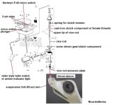
The 280 lift-out unit's "ram" is actually a "vice rod" with a double Allen style thread at the upper section.
The vice rod is extended/retracted by a rotating cast iron clutch component (also with a female version of the double Allen thread).

Your unit may be equipped with a 2 wire, 3 wire or 4 wire electric motor.

The electric motor is operated in either direction (vice rod extension or retraction) depending on which of the two 5-pin relays are activated by the 3 position helm switch.


2. I took a look at the micro switch, which I believe I was referring to as a relay. Small grey rectangular relay looking thing inside the housing.
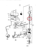
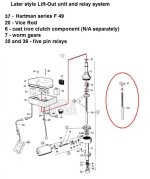
No.... it is an actual micro switch (Hartman F-49) at the upper area of the black plastic housing.
It is being shown as SEQ#30 in the first two images..... and as SEQ#37 in the last image.

It clicks when it gets power.
The Hartman F-49 micro switch will only "click" (circuit open) as the vice rod becomes fully retracted and contacts the micro switch's plunger.

The micro switch does not cut power.... it interrupts the Negative circuit as to stop any further vice rod retraction as to prevent expensive damage to the clutch component (circled in red in the 1st image below)


.
 

Attachments

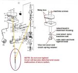
  • Lift unit relay box mounting.jpg
    Lift unit relay box mounting.jpg
    66.8 KB · Views: 498
  • Lift unit vice rod clutch .jpg
    Lift unit vice rod clutch .jpg
    34.3 KB · Views: 600
  • Lift unit vice rod clutch and micro switch .jpg
    Lift unit vice rod clutch and micro switch .jpg
    54.7 KB · Views: 620
Last edited:
OK..... the Standard 280 drive unit does NOT offer Tilt or Power Trim!
The standard 280 drive will be equipped with a Lift Out unit only.
The Lift Out unit is NOT intended to be used with the drive raised up.
However, the 280 PT drive does have power trim and tilt. (not too many of these were produced)

The 280 lift-out unit's "ram" is actually a "vice rod" with a double Allen style thread at the upper section.
The vice rod is extended/retracted by a rotating cast iron clutch component (also with a female version of the double Allen thread).

Your unit may be equipped with a 2 wire, 3 wire or 4 wire electric motor.

The electric motor is operated in either direction (vice rod extension or retraction) depending on which of the two 5-pin relays are activated by the 3 position helm switch.


.

There are 3 wires running into the housing, just like the pictures. Within that black housing I only see one relay/ micro switch. The Hartman f49 as you mentioned. Everything is clean in there connection wise.

It almost has to be the micro switch wouldn't you think? Just because it seems to me like its having issues figuring out "where its at". The switch on the dash for the lift has always worked and the wiring looks correct.

Again with the black housing back in place holding the micro switch down secure and the the vice rod fully retracted, when I flip the switch to raise the drive the vice rod extends out about 1/4-1/2 inch then retracts back in regardless of what position I'm holding the switch at.

thanks for the help and the explodes, it is TRULY appreciated every time :cool:
 
Also
I pulled the relay and tested continuity. With no pressure on the micro switch current flows, but as soon as I depress the micro switch current flow stops. Based on that I would say its not the relay/ micro switch. HMMM
 
You should have 1 micro switch (Hartman F-49) and 2 standard small body 5 pin relays!
I would suggest replacing the 5 pin relays. One wire at a time!!!!!


The trick is to find a 5 pin relay with the small body and without the mounting tang, otherwise they will not fit into the plastic housing.
The OEM are Bosch!

http://www.autohausaz.com/search/pn...1mWC7oqk_tJEQqFUfINH0PNrvx6pUbEBoCHokQAvD_BwE

Remove/Replace one wire only at a time.
Make sure that you see the terminal numbering #30, #85, #86, #87a and #87, and that you do an exact copy of that when reconnecting.

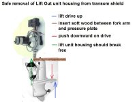
NOTE: DO NOT attempt to remove the lift-out unit body by prying between it's flange and the transom shield.
The housing is cast iron and will break if you do!

Remove the 2 mounting bolts, and then see my image below!
 

Attachments

  • lift unit removal.jpg
    lift unit removal.jpg
    44.2 KB · Views: 405
Last edited:
You should have 1 micro switch (Hartman F-49) and 2 standard small body 5 pin relays!
I would suggest replacing the 5 pin relays. One wire at a time!!!!!


The trick is to find a 5 pin relay with the small body and without the mounting tang, otherwise they will not fit into the plastic housing.
The OEM are Bosch!

http://www.autohausaz.com/search/pn...1mWC7oqk_tJEQqFUfINH0PNrvx6pUbEBoCHokQAvD_BwE

Remove/Replace one wire only at a time.
Make sure that you see the terminal numbering #30, #85, #86, #87a and #87, and that you do an exact copy of that when reconnecting.

NOTE: DO NOT attempt to remove the lift-out unit body by prying between it's flange and the transom shield.
The housing is cast iron and will break if you do!

Remove the 2 mounting bolts, and then see my image below!

Yes, i kind of jumped the gun there before I really got in there to take a look.. The micro switch and 2 20/30amp 5 pin Bosch relays.
I see what your saying about the body size.

Funny thing here is now i got the drive to come up but when I go to put it back down it goes all the way down on its own. As in I let go of the switch and the vice rod continues to retract.

thoughts?


Here is a run-down of what should occur with the AQ series mechanical/electrical Lift-Out unit:

Battery switch ON.
Amber light (if equipped) will be OFF.
When the helm switch is lifted, the relays should active the motor in a direction that causes the vice rod to extend.
This will raise the drive up.
This action can be stopped at any time by releasing the helm switch!
Once the drive begins to lift, the amber light should become illuminated (warning operator of the lifted stern drive).

If the helm switch is kept in the "lift mode" the motor will continue to operate even after the vice rod has become fully extended (drive up).
The motor will continue to operate due to the clutch reaching it's limit as it begins to slip (as designed).

At this point, you should be able to manually push the drive down causing the clutch to slip (again, as designed for protection).

When the helm switch is pushed downwards, the relays should activate the motor in a direction that causes the vice rod to retract, causing the drive to become fully lowered.
This action can be stopped at any time by releasing the helm switch!

When the vice rod becomes fully retracted(drive fully down), several things occur:

1...... the l
atch hooks will grab onto the "set pin" (preventing reverse kick-up and offering impact protection).
2...... the vice rod pressure plate will lose contact with the thrust sleeve (the small sleeve that protrudes thru the suspension fork arm).
3...... the vice rod upper end (not visible) will depress the micro switch, thus opening the Negative circuit, therefor stopping the motor action (as to prevent internal clutch damage).

Again... DO NOT operate the electric motor (as in jumping terminals)
without the micro switch and circuits all connected!

As you have found out, the motor is working........ the vice rod is working....... the clutch is apparently working.

Have you checked the helm switch function?
This will be a momentary 3 position helm switch (On/Off/On).
Is it returning to the middle position (i.e., OFF)?
Is there NO continuity at either of the two outside terminals while in the middle position?


Attachments

  • Lift unit vice rod clutch and micro switch 2.jpg
    Lift unit vice rod clutch and micro switch 2.jpg
    61.7 KB · Views: 322
Side note..... while you may learn to hate the mechanical/electrical lift out unit, the drive itself is nearly bullet proof.
The upper transmission and lower gear units are extremely well designed.
Volvo Penta's patented cone clutch design is by far superior to that of any Dog Clutch stern drive system.

The AQ series got a bad rap due to the lift out unit that was problematic.
However, in the later 80s, the AQ series became available with a true hydraulic Power Trim system.
 
Re: "I flip the switch to raise the drive the vice rod extends out about 1/4-1/2 inch then retracts back in regardless of what position I'm holding the switch at."

You sure??? Flipping the switch UP when the drive is down should cause the rod to extend until you either let go of the switch or the microswitch cuts power to the motor. Flipping the switch DOWN when the drive is down should cause the motor to run, the rod NOT to extend as it slips on the slip clutch.

My advice... check the wiring, wire by wire, to make sure it agrees with the wiring diagram. ALSO.... while all 5 pin relays perform the same function, their "pin out" may not be the same, i.e.. check the mechanical layout contact configuration vs electrical function. In other words, (for example) the pin in the upper right hand corner on two different relays may not have the same function.
 
Last edited:
........................
Re:
"I flip the switch to raise the drive the vice rod extends out about 1/4-1/2 inch then retracts back in regardless of what position I'm holding the switch at."

You sure???
Flipping the switch UP when the drive is down should cause the rod to extend until you either let go of the switch or the microswitch cuts power to the motor.

All due respect....... not quite so!
The Hartman F-49 micro switch interrupts the motor's Negative circuit ONLY during a complete retraction of the vice rod!
In other words, the micro switch function only occurs as (a) the vice rod breaks contact with the m/s plunger, and (b) again when the vice rod makes contact with the m/s plunger.


Flipping the switch DOWN when the drive is down should cause the motor to run, the rod NOT to extend as it slips on the slip clutch.
If all is OK..... the vice rod will extend causing the drive to lift up!

My advice... check the wiring, wire by wire, to make sure it agrees with the wiring diagram.
I agree.... this is important!
Make sure that you are using the correct schematic for the motor type..... I.E., 4 wire motor, 3 wire motor or the 2 wire motor.


ALSO.... while all 5 pin relays perform the same function, their "pin out" may not be the same, i.e.. check the mechanical layout contact configuration vs electrical function. In other words, (for example) the pin in the upper right hand corner on two different relays may not have the same function.
Look carefully at each terminal # as you R&R each wire as you install the new relays.
You will see #30, #85, #86, #87a and #87.
For example....... make sure that the wire that is marked #30 goes back onto the terminal #30 of the new relay, and so on!
 
After some work with he multi-meter

I GOT IT!

it was the wire running from the helm switch to the relay responsible for, I’m assuming moving the drive downward. On his boat it was a brown wire.

Re-routed a new wire to bypass the old dead original (brown) one and Wha-lah!

Thank you to everyone!
Especially Rick!! Man of patience I tell you!
 
Can i get a little help? This is my first time using this website. First time working on boat I just received and it is a 130 Penta motor on a 63 Larson. Can anybody help diagnose and walk me through minor issues I am completely mechanically inclined but I am learning.
 
Casey, this thread was started well over a year ago.
It's always best to start a new thread for your specific question.

Go to the home page for the Volvo Penta forum.
Click on the "+Post New Thread" button that is just above the Forum Home: Volvo Penta Gas Engine Forum
 
Back
Top