FstaRockr Burns
Regular Contributor
Hi all - thought Id start a new thread for this issue. Spent a few hrs today working on the starboard motor in a 68 bertram.. For the life of me I could not figure out what the heck is happening with the multiple timing marks all over the flywheel, one stripe, 4 stripes, 2 stripes! And no 0 - only on the engine plate is there a 0..
I removed plug #1 and buzzed starter till I was on the compression stroke (verified 3 times).. There were 4 marks and a trailing single mark - NO IDEA which one is the actual marker.. Anyway - I tried my best and set the timing by rotating the dizzy against the rotor till I got a good idea of where the spark wd be.
I set the timing according to the intake manifold and it would NOT run.. I tried reversing the firing order stamped on the manifold - and it took almost instantly..
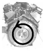
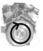
Now my 2nd issue - on BOTH motors the firing order says 1-8-4-3-6-5-7-2 however that firing order does not work on the counter clockwise motor.. The flywheel (as seen from rear looking fwd) rotates clockwise and the rotor moves counter clockwise -
Here is a pic of the intake of the stbd motor (using reverse firing order seems to work much better):

Could using the wrong manifold cause these issues? Stalling / hunting at idle? When I give it throttle is has a smooth sound and seems very powerful.
Here is a pic of the motor - not sure what size? At read of intake there is a big A after the Chrysler..

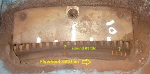
Here are the confusing timing marks on the flywheel:

Can anyone shed some light? The stbd carb went thru the ultra sonic cleaner, blew out - installed a kit.. and on the starboard motor it still struggled to idle.. hunted a little here and there (vac ports plugged).. When I put it on the port motor it ran MUCH better.. the plugs are burning a tan and for the life of me struggling to figure out what the issue is -
Im wondering if someone didnt erroneously install a regular rotation intake manifold on the counter rotation stbd engine and if it wd cause issues?
I removed plug #1 and buzzed starter till I was on the compression stroke (verified 3 times).. There were 4 marks and a trailing single mark - NO IDEA which one is the actual marker.. Anyway - I tried my best and set the timing by rotating the dizzy against the rotor till I got a good idea of where the spark wd be.
I set the timing according to the intake manifold and it would NOT run.. I tried reversing the firing order stamped on the manifold - and it took almost instantly..
Now my 2nd issue - on BOTH motors the firing order says 1-8-4-3-6-5-7-2 however that firing order does not work on the counter clockwise motor.. The flywheel (as seen from rear looking fwd) rotates clockwise and the rotor moves counter clockwise -
Here is a pic of the intake of the stbd motor (using reverse firing order seems to work much better):
Could using the wrong manifold cause these issues? Stalling / hunting at idle? When I give it throttle is has a smooth sound and seems very powerful.
Here is a pic of the motor - not sure what size? At read of intake there is a big A after the Chrysler..
Here are the confusing timing marks on the flywheel:
Can anyone shed some light? The stbd carb went thru the ultra sonic cleaner, blew out - installed a kit.. and on the starboard motor it still struggled to idle.. hunted a little here and there (vac ports plugged).. When I put it on the port motor it ran MUCH better.. the plugs are burning a tan and for the life of me struggling to figure out what the issue is -
Im wondering if someone didnt erroneously install a regular rotation intake manifold on the counter rotation stbd engine and if it wd cause issues?