Logo

Preparing for Swivel Case and Mount Frame replacement

Solamar

Member
1995 BF45

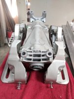
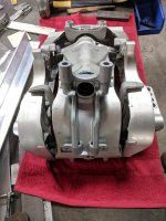
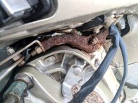
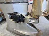
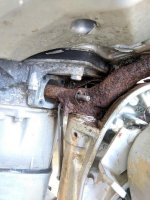
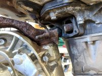
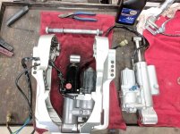
My mount frame is rusted to the point of not having confidence in it's strength (what a terrible design...). Last weekend I was hammering out the top tilt cylinder pin and large chunks of rusted mount frame were falling off.:(

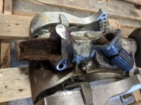
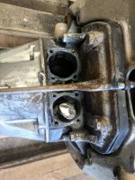
The correct mount frame for my outboard is no longer available, but the 2004+ mount frame is. Comparing parts lists, the 2004 BF40 and 1995 BF45 share almost all parts. The parts not shared (relevant to this project) are the Swivel Case, Mount Frame and Stern Brackets. I lucked out and found the correct Stern Brackets and Swivel Case on ebay (in near new condition). Will order a new Mount Frame and Lower Mount Center Housing as well as a few oddball parts.

Does this sound like the correct procedure?

- Remove lower unit, throttle cable and shift cable
- Support engine with overhead lift
- Remove Upper Rubber Motor Mount Nuts
- Remove Lower Motor Mounts
- Lift off outboard
- Remove tilt cylinder, Pivot (steering) tube, Swivel Case and Stern Brackets
- Re-assemble

I do have the correct Honda shop manual. Any "Gotchas" I should watch for? I'm hoping that by replacing the Swivel Case and Lower Mount Center Housing I'm eliminating most of the expected problems with seized components. Any parts that should be replaced while I'm in there?

Thanks for any insight!

Matt
 
I'm pushing a bit deeper into the fray...

I found a new - takeoff, complete transom mount, swivel, mount frame, trim tilt assembly. Off a 2007 BF50...

I'm 95% sure it will directly bolt to my motor/mid-section. I'm not so sure about the wiring of the tilt/trim and the trim angle sensor. I think the newer engines use the ECM to drive the trim tilt as opposed to the older models using relay/control module. I figure it just needs switched power. Can't be that difficult to figure out, right?
 
Hi,
Yes, it's just a matter of switching 12 v to the motor while reversing polarity at the same time.
 
Getting closer, waiting for a few more parts.

Yesterday I started pre-soaking with PB Blaster to improve my chances. I noticed that the shift rod passes through the swivel case. This screws up my plan of removing the upper and lower motor mounts and lifting the outboard off the swivel case/stern bracket assy.

After removing the lower unit with the lower shift shaft, what do I do with the shift shaft that goes through the swivel case?
 
Well the 2007 new take-off parts didnt happen. The ebayer accepted my offer, took my payment and then sold it to someone else that made a higher offer... At least he refunded my payment.

Back to plan "A"
I bought a swivel mount and transom mount set off ebay from a fresh water motor (about 2004). Look brand new to me. Bought a new frame mount and lower center mount housing (for a 2004) and a few misc pieces and started assembly.

I don't know why Honda designed it this way, but the lower center mount is a substantial press fit onto the splined frame mount. Fortunately I have a hydraulic press, but it took more than I would have guessed. If you are considering changing your frame mount, plan on a new center mount, even with proper tooling pressing an old one off would be unlikely.

Still waiting on a back ordered tilting shaft, should ship tomorrow. Might tear it apart next weekend.
 

Attachments

  • SB1.jpg
    SB1.jpg
    69.6 KB · Views: 288
  • SB2.jpg
    SB2.jpg
    73.1 KB · Views: 285
Last edited:
Here's a shot of the the frame mount that I'm replacing. Not very confidence inspiring...
 

Attachments

  • Rusted Frame Mount.jpg
    Rusted Frame Mount.jpg
    65.4 KB · Views: 439
Finally I am getting around to this project... Had some time on Saturday and started tearing into it.

The lower motor mounts came apart easily, found the largest Black Widow I've ever seen living behind the Starboard MM cover :eek: Wonder how long she's been living there.

I'm not re-using the swivel case or Stern Brackets so I can avoid the nightmare if separating those components. Judging by the look of the pivot tube, they would have to be cut apart.

I knew the upper Motor Mounts were going to be a problem, and they did not disappoint. The rubber mount has a stainless screw inserted from the inside that bolts thru the rusted Frame Mount. I hoped the bolts would slide out, nope, rusted solid. The rubber motor mounts are held into the lower case by a square aluminum cover with four bolts. The inner upper bolts I could just barely get a 1/4" drive 6 pt socket onto, fortunately they popped loose.

Now, the entire assembly (swivel case, transom mount and upper motor mounts) should have slid easily away from the motor. Nope. The rubber mounts were seized into the case.

After prying, wiggling and cursing for a bit I got out the angle grinder with a cut-off wheel and went at it.

Fortunately the upper shift rod that I was concerned about (it goes down through the swivel case) pivots at the top allowing the swivel assembly to be removed without disassembling the upper shift rail.
 

Attachments

  • MM1.jpg
    MM1.jpg
    61.8 KB · Views: 312
  • MM2.jpg
    MM2.jpg
    76 KB · Views: 322
  • MM3.jpg
    MM3.jpg
    81.7 KB · Views: 407
The first picture below shows the Starboard Motor Mount cut from the Frame Mount. It wiggled out after being cut loose.

The second picture is the stuck Port Motor Mount. After drilling a few holes through the rubber and soaking in Kroil I finally got it to come out!

I bought the Honda paint kit (primer, paint, clear coat) to dress things up a bit, Hopefully I'll have time to finish this up over the Christmas break.
 

Attachments

  • MM4.jpg
    MM4.jpg
    64.1 KB · Views: 373
  • MM5.jpg
    MM5.jpg
    86.5 KB · Views: 330
Hit a snafu. The correct Frame Mount for my year is no longer available so after much research I bought a 2004 Frame Mount as well as 2004 Transom Mounts and Swivel Case. Turns out in 2004 Honda redesigned the Power Tilt/Trim ram and my earlier ram does not fit...

Boats.net shows three different Power Tilt/Trim rams for 2004, priced at $800, $900 and $1,000. Any guesses what the differences might be?
 
The alphabetical letters in your model no will tell you what length your motor is then order the yoke according to that length: S-15 Inch ,L-20 Inch, X-25 Inch, XX-30 Inch.
 
Extension case lengths???
Just a guess.

Hopefully someone else here knows for sure.

Not a bad guess ;) The three shaft length models all mount the power tilt-trim in the same brackets (same collapsed length) but I suppose it makes sense that the long shaft models would require more tilt "throw" to get the prop out of the water.
 
The alphabetical letters in your model no will tell you what length your motor is then order the yoke according to that length: S-15 Inch ,L-20 Inch, X-25 Inch, XX-30 Inch.

Mine is a LRTA. Unfortunately the Boats.net lookup does not specify which tilt/trim is a S, L or X. Would make sense for the S to be the cheapest and the X to be the most expensive. I'll give them a call after New Years and see if they have any additional info on the parts.

Thanks for the input!
 
Yeah, very confusing. I looked at both 2004 40hp LRTA & LHTA AS well as 2004 50hp LRTA & XRTA. There are three options for the assembly on all four of those listings when I think there should only be one for each!

When you finally get this sorted out Solamar, you will have some valuable info for anyone trying to do the same thing. WHEW!

Not sure if the info I came up with will be very helpful, or just more confusing...

I called Boats.net and inquired about the differences. They had no idea, but said the correct tilt-trim ram for a 2004 BF40 LRTA is p/n 56000-ZW4-H18. Not even one of the three options listed on their website!

I'm cheep, found one on ebay that was advertised as a 56000-ZW4-H13 (the middle priced ram) and said it was taken off of a BF40. Negotiated a fair price and I'm back in business.

You can see in the picture below (new ram installed, old ram on the table), the ram has been flipped. The motor and bypass valve are now on the opposite side of the transom. Also the entire profile is slimmer.

With a little luck I'll hang her on the back of my Whaler tomorrow ;)
 

Attachments

  • TiltTrim.jpg
    TiltTrim.jpg
    84.4 KB · Views: 299
That's weird! Are you sure that the new one shouldn't be rotated 180 degrees? I'm no expert, but on the 50 hp I've worked on, and all the diagrams show the pump motor on the left side.
 
It is weird. The opening on the Left transom mount to access the manual over-ride is cast over solid. Their is a new, smaller access hole on the Right transom mount to reach the over-ride now.

From what I understand this is a change that started in 2004.
 
Did you sandbags the old One? Shore is SHINY! Are you planning on rebuilding that one or do you just like things real clean?:)
 
Our lakes season opener snuck up on me, gave me the motivation to wrap this up...

Turned out perfect!

While I had everything apart I painted the lower half of the outboard, replaced the old SeaStar steering with a Teleflex No Feedback system and hopefully solved the issue of water in the gear case (corrosion around the shift plug o-ring).

I also raised the engine mount position one hole up (was all the way down). The boat seems more agile now but if I'm trimmed a bit high and punch it the prop can cavitate. Think I like it in this position better though.

Advice if you were to want to tackle this project -
* I'm fairly sure the obsolete "Frame Mount" from the earlier BF40's is a direct swap for the newer frame mounts (I think I used a 2004). the only difference I noticed was the newer part had holes to accept some sort of bracket under the steering arm. So if your swivel mount, transom mount etc are still good, re-use them.

* The shift linkage is a problem unless you remove the power head. I cut my upper motor mounts (they were seized) and if I didn't, I don't think I could have gotten around the shift linkage binding. To re-assemble I took out the upper shift boot, removed the pin holding the shift shaft at the top, and then cursed and fought with needle nose pliers to put it back together. Then split the shift boot to put it back on around the shaft. Removing the upper shift shaft from the top would prevent all these issues.

Hopefully I've added another decade to this old rig!


BF45B.jpgBF45A.jpg
 
Last edited:
Looks awesome Salomar!
That was quite a saga to follow. You must have the heart of a lion to have tackled the job of getting it apart and assessed and then track down replacements and get it all back together and looking that GOOD!
Congratulations sir!
 
Hello! great story and nice perseverance! I am trying to remove the engine to get access to the swivel case, but as you suggested, the gear linkage rod is keeping me from remove the engine completely. Any thoughts on how to do this without taking apart engine to access linkage rod?
 
This whole job is a real treat (NOT!!) in my experience. The one I did was done because the steering tube had rusted pretty badly internally, to the point it was paper thin and crumbling towards the bottom. The area that circlip goes at the bottom was gone completely. Seeing a lot of these (BADLY rusted), and unless I'm missing it somewhere, the part is no longer available, leaving you looking for a used one in decent shape.

To answer your question, the starter and rectifier/regulator (whatever that is), need to be removed to access the shift linkage. I removed the the clips that hold that cross shaft in place (including the neutral start switch and shift detent) THEN, you should be able to pull the linkage up and out of your way. With a little patience, not really that bad a job. Just a lot of dinking around. If you aren't used to dong this kind of thing, a few pics taken during the process may not be a bad idea.

The WORST part of my project was removing that lower collar from the steering tube. It's splined for some reason, making that part of the job a real treat. Once that's off, the rest of the job is easy. Make sure those splines are spotless and well lubed for reassembly, and it memory is serving me properly, the splines are keyed so that collar must be rotated to the proper position to be reinstalled. ONE of those splines is a little wider.

You may luck out, but it took me at least an hour of beating on that lower collar to remove it from the pivot/steering tube......

Best of luck! -Al
 
Last edited:
Ok - that makes sense. I was trying to avoid too much dinking around, but it's unavoidable here, and I'm used to it at this point. I think the components are in decent shape and just need a solid cleaning. That splined tube fitting does make me nervous!

The steering is pretty sticky, and I have done absolutely everything to loosen it up (tapped in more zerk fittings, greased, heated, degreasers, penetrating oil, more heat, more grease) but it is still not getting the free movement necessary for comfortable steering so this is my next option.
 
Sometimes you just gotta do what you gotta do. Put your patience hat on and dive in. The HARDEST part of ANY job is very often just starting on it! -Al
 
Back
Top