Logo

290 DP Upper Gear oil seal replacement

mike77cj

Regular Contributor
I need to replace the oil seal on a 290 DP upper gear unit. The unit utilizes a crush sleeve on the drive gear.

Questions:

1. I have read some people replace the oil seal without installing a new crush sleeve. They simply tighten the torx bolt +5 ft-lbs. Though not the 'proper way', this would say a great deal of time. What are the thoughts and comments on this approach?

2. Is there a torque specification for the bolt fastening the drive gear to the u-joint yoke, or is it simply incrementally tightened until proper preload is achieved (1.10 - 1.76 lbs for used bearings)? I can acquire a rough value of the existing tightening torque by using a torque wrench during disassembly, but this would be fuzzy at best.

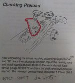
3. Could someone explain the bearing preload measuring procedure to me (attached below)? Do you simply lock the u-joint in a vise, hold the drive gear in your hand to resist movement, tie a string around the bearing box connected to a spring scale and pull? 1.10 - 1.76 lbs seems so low I would think this is difficult to accomplish with great precision.....
Bolt torque.jpg

Thanks for reading and offering any help!

Mike
 
I will respond in blue font!

I need to replace the oil seal on a 290 DP upper gear unit. The unit utilizes a crush sleeve on the drive gear.
Only the "A" and later transmissions use a "crush sleeve" or "pre-tension sleeve" to control bearing separation and the rolling torque value.
If you have an "A" transmission, you are correct!

Questions:

1. I have read some people replace the oil seal without installing a new crush sleeve. They simply tighten the torx bolt +5 ft-lbs. Though not the 'proper way', this would say a great deal of time. What are the thoughts and comments on this approach?
With any "run-in" or "used" bearings in a bearing box affair, we can always slightly increase the roller torque value...... so in that regard, yes....... you are correct, but you will NOT see this written in any service manual!

2. Is there a torque specification for the bolt fastening the drive gear to the u-joint yoke,
You are referring to the universal shaft's male yoke....... correct?

or is it simply incrementally tightened until proper preload is achieved (1.10 - 1.76 lbs for used bearings)?
That is correct. Pay attention to the rolling torque value..... NOT the torque applied to the bolt!!!!!

I can acquire a rough value of the existing tightening torque by using a torque wrench during disassembly, but this would be fuzzy at best.
Yes...... Fuzzy at best!
You'll do better if you were to take a Pre-Disassembly rolling torque reading...... and then slightly increase this when going back together.

3. Could someone explain the bearing preload measuring procedure to me (attached below)? Do you simply lock the u-joint in a vise, hold the drive gear in your hand to resist movement,
You would clamp the universal drive shaft into the bench vice. With the shaft clamped, there is no need to additionally hold the main drive gear.

tie a string around the bearing box connected to a spring scale and pull?
That is correct!
Keep in mind that with a new seal installed, this increases the resistance some.


1.10 - 1.76 lbs seems so low I would think this is difficult to accomplish with great precision.....
Just make sure that you are reading the data from a Volvo Penta OEM work shop manual, and NOT from a Seloc or a Clymers.
Also make sure that you are looking at data for the correct transmission....... Pre-A or A!


View attachment 16024

Mike, a few suggestions:

....... when you have the main drive gear out and the seal surface washer in hand..... look very closely at the seal surface. There can be NO swirl marks or anything that would disturb the seal's lip from a good seal! Swirl marks (in the wrong direction) from polishing can work against us!

...... while the main drive gear/bearing box is out....... it is a great time to remove the two "driven" gears and to lap the sliding sleeve into each gear cup.
(there are several Does/Donts to this....... and I can you help if interested)


....... make certain that none of the shims that you found underneath the transmission have been misplaced. These must go back as they were.

....... hopefully you did not pull the entire stern drive in one unit. If you did, hang the Intermediate housing (and lower gear unit) by itself, and install the transmission separately and LAST!

....... set your gear oil drain plug with a hand held impact driver...... just several mild blows.

....... for the Duo Prop...... be sure to use GL-5 or equivalent gear oil.
 
Rick - thank you for the quick response. Work obligations kept me away from the forum / outdrive until today.

I did remove the entire drive from the boat because I am troubleshooting metal shavings on the drain plug. Some quick background info:

1. The boat is a recently new-to-me 2001 with a total of three owners.
2. The drive in question was replaced with a rebuilt unit in June of 2012 by Owner #1.
3. Owner #2 replaced the propeller shaft OR entire lower unit in July of 2015. (I have inquired as to which route was taken.)
4. I discovered metal shavings on the drain plug when I surveyed the vessel prior to procurement. After purchasing I drained the oil, flushed the drive with diesel and filled with GL5. I then ran the boat for 1.5 hours. Once again metal filings were discovered on the drain plug.
5. The lower unit is a 1.95:1 ratio, and the upper gear has a 22 count drive gear, 23 count motion gear resulting in an overall outdrive ratio of 2.04.

Today I removed the clamp ring from the double bearing box and discovered a few things:

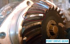
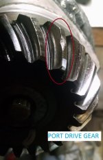
A. One of the drive gear teeth is chipped.
B. Drive gear wear pattern seems to be OK.

Drive Gear.jpgDrive Gear 2.jpg

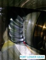
The lower gear in the bearing box (forward motion) appears to have wear slightly forward on the gear face. I assume the shim pack on the lower gear and possibly the clamp ring will need amendment.

Lower Gear.jpg

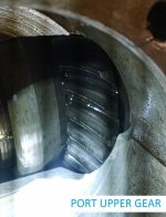
The upper gear (reverse) wear pattern seems to be okay.

Upper Gear.jpg

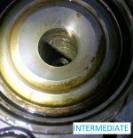
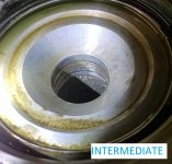
The cavity in the intermediate housing around the vertical shaft is trashed. There are many gouges. At first I thought this may be the source of the metal, but this housing is aluminum and shards would not stick to the magnet on the drain plug.

What is causing / could have caused this damage? If a new lower unit was installed by Owner #2 and proper Lower Unit to Intermediate shimming was NOT done, could that be the problem? (Wouldn't I have to pull the vertical shaft bearing and race to take measurements and add/remove shims?) The metal basket in the rear of the lower unit had a few metal flakes in it, but nothing excessive.Intermediate 2.jpgIntermediate.jpg

The pinion gear in the lower unit looks good, the bearing on the vertical shaft looks good, the rear drive gear and forward drive gear in the lower unit also look good.

(I will post pics shortly.)

What do you guys think about the chip on the drive gear?

Now I am not sure if I should bother replacing the upper gear oil seal at all, or if I should source a new/rebuilt upper....

Do all 290 DP uppers have a 22/23 tooth count?

Thanks for the help!

Mike
 
Last edited:
My SWAG... lower unit sustained damage got replaced... never checker upper for damage... or ignored damage.

IF it were my boat..
1) Inspect lower gears for subsequent damage from the metal floating around. Pay particular attention to the bearings.
2) Replace the upper.
 
Capt Bob - I tend to agree with you. I suspect the yard that changed lower parts simply slapped them in, paid no regard to shimming, did not flush the drive to remove metal, added new oil and sent the boat on it's way. The chip on the upper drive gear is probably a result of metal shards from the prior lower unit failure meshing between teeth.
 
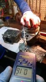
I ordered an inexpensive - and rather accurate, digital spring scale from Amazon to check the bearing preload. I clamped the u-joint assembly in a vise, asked my lovely assistant to hold the drive gear, tied and taped string to the clamp ring, wrapped the string 4-5 times around the ring, attached the scale and pulled the string with constant force to rotate the ring. It took a bit of practice to apply a steady force, but after 8-10 attempts the results were consistent in the 0.80 - 1.00 lbs range.

The Volvo manual states 500 - 800 grams (1.10 - 1.76 lbs) is desirable for used bearings.

Preload.jpg

I then used a torque wrench to attempt tightening the drive gear bolt in 5 ft-lbs increments. The bolt moved between 50 and 55 ft-lbs. This is the "fuzzy method" I described above.

Next I removed the bolt and drove free the u-joint yoke.

Rick - The o-ring on the washer (the u-joint yoke washer) is toast, there does not appear to be any swirls, but there are some nicks on the washer.

"....... when you have the main drive gear out and the seal surface washer in hand..... look very closely at the seal surace. There can be NO swirl marks or anything that would disturb the seal's lip from a good seal! Swirl marks (in the wrong direction) from polishing can work against us!"

Which direction do you recommend polishing this washer? (I do have a new one - with o-ring, on hand.)

The oil seal was complete toast.

NOTE: This seal crosses to an SKF 692517 if you wish to source from your local NAPA.

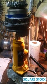
Behind the oil seal was a good amount of metal - steel, shards, so I decided to press out the drive gear. To do this i cut a section of square stock, drilled holes in it to match the distance between two clamp ring bolts, cut some threaded rod and attached one end to the square stock and the other end to the clamp ring. I then placed a hydraulic jack between the clamp ring and square stock creating an "in-place press". A few pumps and the gear was out.

Press.jpg

The two bearings look to be in good shape. There are no signs of blown out cages or damaged balls.

I am not sure if I should tear down the bearing box, inspect the lower and upper gears, lap the cone cups, reassemble the whole works and put the drive back together and run it. All the while sourcing a new / rebuilt upper unit....
 
..............................................
Rick - thank you for the quick response. Work obligations kept me away from the forum / outdrive until today.

I did remove the entire drive from the boat because I am troubleshooting metal shavings on the drain plug.
OK..... but when you go back together, hand the Intermediate housing first, and the transmission last.

Some quick background info:

1. The boat is a recently new-to-me 2001 with a total of three owners.
2. The drive in question was replaced with a rebuilt unit in June of 2012 by Owner #1.
3. Owner #2 replaced the propeller shaft OR entire lower unit in July of 2015. (I have inquired as to which route was taken.)
4. I discovered metal shavings on the drain plug when I surveyed the vessel prior to procurement. After purchasing I drained the oil, flushed the drive with diesel and filled with GL5. I then ran the boat for 1.5 hours. Once again metal filings were discovered on the drain plug.
Metal shavings and filings..... or metallic debris?

5. The lower unit is a 1.95:1 ratio, and the upper gear has a 22 count drive gear, 23 count motion gear resulting in an overall outdrive ratio of 2.04.
NOT Quite!
With exception to the Diesel Engine DP-E drive transmission, all upper transmissions are of the same reduction.
The DP lower unit is not a 1.95:1 reduction by itself.
The 1.95:1 is an "over-all" reduction, or in other words, it is a combination reduction of transmission and lower unit.


Today I removed the clamp ring from the double bearing box and discovered a few things:

A. One of the drive gear teeth is chipped.
I see that..... not good!

B. Drive gear wear pattern seems to be OK.

View attachment 16049View attachment 16050

The lower gear in the bearing box
FYI....... the only gear in the bearing box is the "drive" gear.

appears to have wear slightly forward on the gear face. I assume the shim pack on the lower gear and possibly the clamp ring will need amendment.
You will need to use a gear pattern die, such as Prussian Blue, to check the pattern.
See the OEM work shop manual for the correct wear pattern.


View attachment 16051

The upper gear (aka "driven" gear) wear pattern seems to be okay.

View attachment 16052

The cavity in the intermediate housing around the vertical shaft is trashed. There are many gouges. At first I thought this may be the source of the metal, but this housing is aluminum and shards would not stick to the magnet on the drain plug. What is causing / could have caused this damage?
Those gouges are likely from a previous gear failure. They should not affect the Intermediate housing performance.


If a new lower unit was installed by Owner #2 and proper Lower Unit to Intermediate shimming was NOT done, could that be the problem?
Yes..... it would certainly cause a problem.

(Wouldn't I have to pull the vertical shaft bearing and race to take measurements and add/remove shims?)
Yes! This would be your A and B dimensions.


The metal basket in the rear of the lower unit had a few metal flakes in it, but nothing excessive.


View attachment 16053View attachment 16054

The pinion gear in the lower unit looks good,
This is called a "drive" gear.

the bearing on the vertical shaft looks good,
I am not following you re; this one.


the rear drive gear and forward drive gear in the lower unit also look good.
These are the two (2) "driven" gears.

(I will post pics shortly.)

What do you guys think about the chip on the drive gear?
It will compromise the gear's strength.

Now I am not sure if I should bother replacing the upper gear oil seal at all, or if I should source a new/rebuilt upper....

Do all 290 DP uppers have a 22/23 tooth count?
Again.... with exception to the Diesel Engine DP-E drive, all transmissions are of the same reduction.

Thanks for the help!

Mike

I ordered an inexpensive - and rather accurate, digital spring scale from Amazon to check the bearing preload. I clamped the u-joint assembly in a vise, asked my lovely assistant to hold the drive gear, tied and taped string to the clamp ring, wrapped the string 4-5 times around the ring, attached the scale and pulled the string with constant force to rotate the ring. It took a bit of practice to apply a steady force, but after 8-10 attempts the results were consistent in the 0.80 - 1.00 lbs range.

The Volvo manual states 500 - 800 grams (1.10 - 1.76 lbs) is desirable for used bearings.

View attachment 16059

I then used a torque wrench to attempt tightening the drive gear bolt in 5 ft-lbs increments. The bolt moved between 50 and 55 ft-lbs. This is the "fuzzy method" I described above.

Next I removed the bolt and drove free the u-joint yoke.

Rick - The o-ring on the washer (the u-joint yoke washer) is toast, there does not appear to be any swirls, but there are some nicks on the washer.

"....... when you have the main drive gear out and the seal surface washer in hand..... look very closely at the seal surace. There can be NO swirl marks or anything that would disturb the seal's lip from a good seal! Swirl marks (in the wrong direction) from polishing can work against us!"

Which direction do you recommend polishing this washer? (I do have a new one - with o-ring, on hand.)
If you are not sure about polishing and the swirl marks that I've mentioned, by all means install the new one.
Keep in mind that this will cause a different rolling torque value if you plan to re-use the pre-tension sleeve (aka crush sleeve).

The oil seal was complete toast.

NOTE: This seal crosses to an SKF 692517 if you wish to source from your local NAPA.
Not all part cross-overs give us the same style seal lip. Use caution.

Behind the oil seal was a good amount of metal - steel, shards, so I decided to press out the drive gear. To do this i cut a section of square stock, drilled holes in it to match the distance between two clamp ring bolts, cut some threaded rod and attached one end to the square stock and the other end to the clamp ring. I then placed a hydraulic jack between the clamp ring and square stock creating an "in-place press". A few pumps and the gear was out.
Well.... that worked, but why not use a hydraulic press?

View attachment 16061

The two bearings look to be in good shape. There are no signs of blown out cages or damaged balls.
In order to fully examine the 31307 inner race, it must be sacrificed and removed.

I am not sure if I should tear down the bearing box,
You have already taken the bearing box apart!

inspect the lower and upper gears,
Do you mean the two transmission "driven" gears?

lap the cone cups,
I generally lap the bronze sliding sleeve into each respective gear cup.
(for transmissions with the steel sliding sleeve and coated gear cups...... NO! )


reassemble the whole works and put the drive back together and run it. All the while sourcing a new / rebuilt upper unit....
If so, gently polish or ease the edges of the chipped gear area.
 
Once again Rick, thank you for the thorough response.

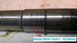
This morning I confirmed the lower unit drive gear and two driven gears are in good shape. The inner propeller shaft has radial scoring - aka a groove, in two places where the seals ride. If I reassemble I will pressure test the unit, but what do you guys think of this:

Inner prop shaft.jpg

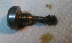
The metal I found on the drain plug was similar to "metallic hair". This was the case during survey, and again after an oil change. The photo below was taken this morning, after the oil was drained last week and the plug cleaned. This "metal hair" was picked up just rotating the gears by hand. (NOTE: SIGNIFICANTLY more metal was on the plug the first two removals - at least 1" of metal clinging to the end.)

Drain Plug.jpg

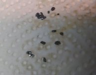
The metal flakes, or shards, that I found behind the oil seal, and in the strainer basket, looked like this:

Metal shards.jpg

As Capt Bob stated, I suspect these are leftover from the prior lower unit gear failure.

"the bearing on the vertical shaft looks good,
I am not following you re; this one. "

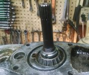
The bearing I was referencing is this one, on the lower unit:

Vertical shaft.jpg

Rick, could you explain this a bit further:

Which direction do you recommend polishing this washer? (I do have a new one - with o-ring, on hand.)
If you are not sure about polishing and the swirl marks that I've mentioned, by all means install the new one.

I suspect I would polish the backside of the u-joint yoke, and the face of the washer BEFORE installing a new o-ring in the groove. I imagine the motion would be clockwise to match the rotation of the PDS. I'm thinking steel wool and/or some light emery cloth?

I fabricated my "in-place press" because I do not own a press, and my workshop is filling up with Harbor Freight one-time tools... :)

As you stated Rick, the overall reduction of the drive is based on:

Upper drive gear teeth = 22 Upper driven gear teeth = 23 Upper ratio = 1.04
Lower drive gear teeth = 16 Lower driven gear teeth = 30 Lower ratio = 1.88
Total drive ratio = (1.05) * (1.88) = 1.95

So I should be fine sourcing a used/rebuilt/new upper from a DPA, DPB, DPC or DPD drive, correct?

How do you recommend I polish / ease the chip? Gently smoothing with 320/400/600 grit sandpaper, then polish with steel wool? I understand the intent is to round out sharp edges to eliminate stress concentrations.

I think I read the drive and driven gears need to be replaced as a set. The cost of a new gear set seems greater than a total rebuilt upper, so this doesn't seem practical. Could I install a used drive gear, re-use the lower and upper driven gears and just re-shim everything?

How much of a gamble do you guys think it is to run the drive with that chipped tooth?

Thanks again.
 
..................................
Once again Rick, thank you for the thorough response.

This morning I confirmed the lower unit drive gear and two driven gears are in good shape. The inner propeller shaft has radial scoring - aka a groove, in two places where the seals ride. If I reassemble I will pressure test the unit, but what do you guys think of this:

View attachment 16062

Polish the surface.

The metal I found on the drain plug was similar to "metallic hair". This was the case during survey, and again after an oil change. The photo below was taken this morning, after the oil was drained last week and the plug cleaned. This "metal hair" was picked up just rotating the gears by hand. (NOTE: SIGNIFICANTLY more metal was on the plug the first two removals - at least 1" of metal clinging to the end.)

View attachment 16063

The metal flakes, or shards, that I found behind the oil seal, and in the strainer basket, looked like this:
Not good!

View attachment 16064

As Capt Bob stated, I suspect these are leftover from the prior lower unit gear failure.
I would find it hard to believe that a mechanic would not flush out the gear case.

"the bearing on the vertical shaft looks good,
I am not following you re; this one. "

The bearing I was referencing is this one, on the lower unit:

View attachment 16065

OK..... that is a tapered roller bearing that checks and controls vertical shaft up-lift. Look closely at the bearing race surface.

Rick, could you explain this a bit further:

Which direction do you recommend polishing this washer? (I do have a new one - with o-ring, on hand.)
If you are not sure about polishing and the swirl marks that I've mentioned, by all means install the new one.

I suspect I would polish the backside of the u-joint yoke,
NO....... the seal surface washer mates to the FWD end of the male yoke. It becomes oil tight via the small O-ring.
The actual seal rides on this washer..... not the yoke.


I imagine the motion would be clockwise to match the rotation of the PDS.
Yes..... however, if during polishing swirl marks are created in a direction that would allow the seal to wipe oil FWD (towards the bow of the boat), you will encounter an oil leak. It would be similar to building a REV RH Rotation engine using STD LH Rotation crankshaft seals.


So I should be fine sourcing a used/rebuilt/new upper from a DPA, DPB, DPC or DPD drive, correct?
There were 3 sizes or driven gear bearing retainers used.
Only the mid size "driven" gear bearing retainers will fit into your Intermediate housing.
In other words...... a C or later transmission will not work.


I think I read the drive and driven gears need to be replaced as a set.
Correct...... you cannot purchase only one hypoid gear.

The cost of a new gear set seems greater than a total rebuilt upper, so this doesn't seem practical. Could I install a used drive gear, re-use the lower and upper driven gears and just re-shim everything?
NO!
No offense........ but where would you find this one drive gear by itself........ and if you did find a set, why would you not use all 3 matching gears?

How much of a gamble do you guys think it is to run the drive with that chipped tooth?
I would use a small die grinder and would ease the chipped tooth edges.
 
Last edited:
Thanks Rick!

I spoke to Owner #2 today and he said the former lower unit catastrophically failed in April of 2016. He dropped that lower, installed a used lower, ran the boat for a day, changed the oil, ran the boat a week and changed the oil a second time. I'm now confident the shards are from improper flushing. As for the "metallic hair" on the drain plug, I don't know...

Owner #2 did NOT shim the lower to the intermediate, so perhaps this is causing the lower driven gear in the upper to wear toward the front of the teeth.

Based on your response above, I've put together a game plan:

1. Polish propeller shaft grooves
2. Replace propeller shaft seals
3. Shim lower to intermediate
4. Polish chipped upper drive gear with Dremel
5. Press upper drive gear back onto bearing and reassemble upper
6. Hang lower/intermediate on boat, then install upper
7. Source a rebuilt / used DP-C, DP-D, DP-E (22/23) upper

The Volvo manual states to leave "1 mm between the crush sleeve and bearing" when you press the drive gear back into the bearing. Since you can't see, or measure this distance, any suggestions for accomplishing this? I plan to re-use the old crush sleeve and increase preload +0.2 lbs, but I don't want to smoosh the crush sleeve with the bearing.

There is a shop in my town that has (had) a bunch of older AQ drives and some early DP drives in pieces. Ten years ago I sourced some parts for a 280, and remember seeing quite a few u-joint / clamp ring / drive gears in a pile without the rest of the upper unit, so that's where I was going to look for a drive gear / gear set. Shot in the dark at best.

Thanks again for taking the time to reply and offering so much help.

Mike
 
............................
Thanks Rick!

I spoke to Owner #2 today and he said the former lower unit catastrophically failed in April of 2016. He dropped that lower, installed a used lower, ran the boat for a day, changed the oil, ran the boat a week and changed the oil a second time. I'm now confident the shards are from improper flushing. As for the "metallic hair" on the drain plug, I don't know...
As you may know, the lower unit pumps the cooler gear oil up to the transmission where it then removes heat, and then gravity drains to the lower again. This means that any metallic debris is also pumped up to the transmission.

Owner #2 did NOT shim the lower to the intermediate, so perhaps this is causing the lower driven gear in the upper to wear toward the front of the teeth.
Perhaps.
The A and B dimension and proper shimming is a MUST!


Based on your response above, I've put together a game plan:

1. Polish propeller shaft grooves
2. Replace propeller shaft seals
3. Shim lower to intermediate
4. Polish chipped upper drive gear with Dremel
5. Press upper drive gear back onto bearing and reassemble upper
Why not replace these two industry standard 30207 and 31307 bearings?

6. Hang lower/intermediate on boat, then install upper
7. Source a rebuilt / used DP-C, DP-D, DP-E (22/23) upper
again...... there are 3 driven gear bearing sizes. You must stay within the same model ranges.
And please understand that the E transmission reduction is unique.


The Volvo manual states to leave "1 mm between the crush sleeve and bearing" when you press the drive gear back into the bearing. Since you can't see, or measure this distance, any suggestions for accomplishing this? I plan to re-use the old crush sleeve and increase preload +0.2 lbs, but I don't want to smoosh the crush sleeve with the bearing.
You will NOT see this written in any shop manual........ but when placed over a hardened shaft, the pre-tension sleeve can be tapped out and expanded some. This will increase it's length.

There is a shop in my town that has (had) a bunch of older AQ drives and some early DP drives in pieces. Ten years ago I sourced some parts for a 280, and remember seeing quite a few u-joint / clamp ring / drive gears in a pile without the rest of the upper unit, so that's where I was going to look for a drive gear / gear set. Shot in the dark at best.
Yes.... a shot in the dark.

Thanks again for taking the time to reply and offering so much help.
You are very welcome.
 
Is it normal to have to press the lower unit inner propeller shaft into the forward driven gear during assembly? The shaft goes in approximately 3/8" with relative ease, but then I have to press the remaining portion of the splined shaft into the gear by equally tightening the two bolts on the bearing carrier assembly.

I used a slide hammer connected to the tail of the inner propeller shaft to disassemble the unit, and had to again do the same during assembly to check gear contact (I did not replace any bearings or gears in the lower unit, and left the shims alone, but figured while I had it apart I would check contact pattern).

After assembly the preload increased a noticeable amount. I am a bit confused by this, since I did not alter any shims. I did clean the face of the lower unit housing, and inner face of the bearing carrier assembly with light sandpaper to remove gasket maker and corrosion, but I do not think I took a measurable amount of material off.

Volvo states the preload should be 10.6 - 20.3 in. lb when rotating the shaft 1 rev/s. Knowing the diameter of the outer shaft is 1.735", could I wrap a string a few times around the shaft, attach the digital spring scale and look for X lbs of force, where:

20.3 in. lb = (1.735/2) in. * X lb
X(max) = 23.4 lb
X(min) = 12.2 lb

I do not posses special tool 884830 (circled below), but figure checking preload without it should be relatively close.

lower preload.jpg

Is there any way to remove the pinion gear and vertical shaft without special tool 884267-6? I welded a socket to a splined coupler to turn the vertical shaft and remove the pinion nut, but I'm scratching my head as how to pull the shaft 'up' and free it from the splined pinion. (I want to remove the pinion so I can remove the forward gear of the lower unit and inspect the bearing, race and shims.)

Thanks for the help.
 
UPDATE:

Evidently I took more material off the lower unit housing and bearing carrier assembly than I thought when I cleaned them with sandpaper. After torquing the two bearing carrier assembly bolts down to 30 ft*lb, I needed to apply a 36 lb force to the shaft to induce rotation. I loosened the the two bolts holding the assembly evenly until the shaft rotated with 14 lb of force. I then inserted a feeler gauge and recorded 0.18 mm between the lower unit housing and the bearing carrier. I pulled the bearing carrier, drove out the aft driven gear race and measured the two shims. They were 0.14 mm and 0.22 mm. I removed the 0.22 mm shim and reassembled.

I now have shaft rotation applying a 12 lb of force.

As mentioned above, I do not posses the special tool to install the vertical shaft tapered bearing race - with shims, to further preload the assembly. I figure once I assemble the intermediate to the lower unit - with proper shims, the preload will increase and I expect it to be within the required range.

My idea of checking preload with a spring scale attached to string on the outer shaft seemed to work. I tried this on a fully assembled drive and consistently recorded 20.1 lb of force at 1 rev/s. Granted this drive was assembled and the intermediate house race was preloading the tapered bearing of the vertical shaft, but the math fell right in place.
 
Last edited:
Back
Top