Logo

points burnout

doc_2048

Member
1977 Glasply 3.0 l 140 GM. I have been burning up points and even tried a electronic ignition with no luck. All seems ok and will run fine until i hit a big wave that gives a jolt, then in about 5 minutes she will start stuttering, missing, and losing power until she will finally die all together. The old original tack was showing erratic reading looking like maybe a short. Put in a new one and it reads low rpm,s. Did not have a chance to put the dwell meter on it to see if i am getting a false reading on tach. I was hoping by replacing the tach i would solve my problem. Would a bad ground wire cause the points to burn? thanks in advance
Dell
 
1977 Glasply 3.0 l 140 GM. I have been burning up points and even tried a electronic ignition with no luck. ........ Would a bad ground wire cause the points to burn? thanks in advance
Dell

I'm confused.... an electronic ignition that still has points... did you install one of those Capacitive Discharge "booster" types.

Re: bad ground and points. No... not really. A missing or defective capacitor or a capacitor without a good connection to ground would do this. Point life with a defective or missing capacitor ( or the wrong one!) gets alarmingly brief...

Other things.... missing resistor if one is called for... shorted coil ( or wrong coil). Also...check point gap, i.e. how far the points are open when the "Cam folllower" plastic thingy on the points themselves is at the high point of the metal cam on the distributor shaft.
 
Last edited:
Several issues possible

1. does distributor shaft "wobble" and it will be worse when engine is warm. This is due to distributor being on an angle. This could take a point gap set up when cold and cause the points to either open more or close.

2. if this issue occurs when you hit a big wave then I would think a bad or weak connection. You might have to inspect the entire engine wiring harnes to see if you have a bad connection.

3. The shift interrupter switch may be an issue. this is designed to activate when shifting out of gear only but if the switch is possibly defective or adjusted incorrectly it could activate or be activated during the conditions you describe.

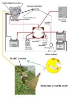
4. Point burn out would be mostly due bad ground, bad condenser, lack of grease on distributor cam lobes or to a lack of the ballast resistor. In this case the ballast resistor is a long wire in the engine wire harness (Approximately 3 feet long) and is not a normal copper wire. It has a resistance value of Approx, 2 ohms. With out it you will not only burn out the coil but also burn up the points. So if someone has rewired the coil + this could be your issue.

5. Main wire harness connector at engine (large black connector). Is this loose fitting? have you removed it and looked at the pins and sockets? if so are they clean? are the pins open? if they are closed you can carefully pry them apart to open them up a bit for better contact. Typically the large connector should have a hose clamp on it and tightened just enough to ensure good pin to socket contact.


Your "new" tach issue could be you have the set point on the back of it wrong. there should be a switch, 4, 6 ,8 and you should be on 4.
 
.................... Would a bad ground wire cause the points to burn? thanks in advance
Dell
Dell, there is no ground per 'se in a 12 vdc system. Only Positive and Negative.

The ignition system contact points complete the ignition coil's primary winding circuit by taking it to Neg with a capacitor being used for current storage.
This is refered to as the coil saturation duration.
When the contact points break, the electrical field collapses causing a secondary high voltage for each spark plug.


A missing or defective capacitor or a capacitor without a good connection to ground would do this. Point life with a defective or missing capacitor ( or the wrong one!) gets alarmingly brief...

Other things.... missing resistor if one is called for... shorted coil ( or wrong coil). Also...check point gap, i.e. how far the points are open when the "Cam folllower" plastic thingy on the points themselves is at the high point of the metal cam on the distributor shaft.
I agree with Bob re; the capacitor.

Also, point Gap is an estimate only of correct dwell angle. Use a dwell meter when adjusting the contact points.


As per Jack's #1, #3, #4 and #5. These are good suggestions.
 
Ummmmmmmmm

yes there is a ground...........that is what the condenser wire lead connects to...........without it the condenser becomes useless....................

the ground path is through the hold down clamp on the distributor and then through the ground stud on back of engine to battery -


See picture!!
 
Ground refers to Earth Ground, as in AC (alternating current).
A 12 vdc system offers a Positive and Negative only and with No Earth Ground being necessary!

And yes...... before you do it........ you will be able to show us many 12 vdc wiring schematics that refer to "ground".
This is an age old misnomer!

This is similar to calling an Engine a Motor!


.
 
Last edited:
Ummmmmmmmm

yes there is a ground...........that is what the condenser wire lead connects to...........without it the condenser becomes useless....................

the ground path is through the hold down clamp on the distributor and then through the ground stud on back of engine to battery -


See picture!!


Correction..........the base plate where the points mount is the grounded surface and is where the condenser body/hold down clamp connects as well.


The Negative path is referred to as ground..............period.

In this case it is a chassis ground.

So MR wizard...............why would you feel need to add this BULL SH!T to this post AGAIN?
 
""And yes...... before you do it........ you will be able to show us many 12 vdc wiring schematics that refer to "ground".""

Refer to the schematic picture I uploaded. It clearly has the CHASSIS ground symbol at the Distributor body!!!!!!!!!!!!!!!!!!!!!!!!
 

Correction..........the base plate where the points mount is the grounded surface and is where the condenser body/hold down clamp connects as well.


The Negative path is referred to as ground..............period.

In this case it is a chassis ground.

So MR wizard...............why would you feel need to add this BULL SH!T to this post AGAIN?

NO BULL SH!T to it. I have spent years educating myself on this.
Perhaps spend a bit of time yourself learning more about DC current -vs- AC current, and the history behind the two.


.
 
""And yes...... before you do it........ you will be able to show us many 12 vdc wiring schematics that refer to "ground".""

Refer to the schematic picture I uploaded. It clearly has the CHASSIS ground symbol at the Distributor body!!!!!!!!!!!!!!!!!!!!!!!!

Yes, and it is clearly an age old misnomer.

As I said, you could find schematic after schematic, and diagram after diagram, that uses the term "Ground" in lieu of Negative.


.
 
Here is schematic for a 12 DC system with an Earth Ground.
Make sure that you drive the grounding rod into the earth at a depth of approximately 8 feet.
 

Attachments

  • MBSS and Ground for some guys.jpg
    MBSS and Ground for some guys.jpg
    61.8 KB · Views: 65
The IEEE ( Institute of Electrical and Electronic Engineers) standard as well as the international standards, allow a "ground" symbol in schematics to refer to the "negative" (in single voltage systems) or "return" in multiple voltage systems. For DC systems a ground symbol has three parallel horizontal lines and (often) a dot. For AC "ground" (green wire) the symbol is three (or more) diagonal vertical lines "capped" with a single horizontal line....
 
The point here is, this hole electrical 101 is not of any importance for this person who posts an issue with a boat.

Again unneeded information that will only cause confusion.

if you want to flaunt your "Electrical theory expertise" go to an electrical forum.

I can guarantee I have forgotten more about electrical theory then most of you will ever know regardless if you can copy and paste or regurgitate the information from your deep caverns!!

I have almost 30 years background in it but I don't flaunt it...........I actually draw electrical schematics as part of my job.........so I know the symbols...

I keep it in street terms for those who post here............KISS
 
Hi I see we have a heated discussion. All good info, trying to gather all info and get busy on testing. Sorry if there was confusion on my install of electronic ignition. It was my last attempt, going back to points until i can get a handle on this. In the past i have had good info from all who has answered my recent post. Thanks Guys
 
I am going to search for ground problems and trying to identify the ballast resistor. To start with. I have only burnt up 4 sets of points and one electronic ignition. Better order more sets. :eek:
 
I am going to search for ground problems and trying to identify the ballast resistor. To start with. I have only burnt up 4 sets of points and one electronic ignition. Better order more sets. :eek:


Earth Vs ground? Who cares.

If you have battery Voltage at your points while the ENGINE is running you have a problem...The ballast lowers voltage the the points ignition system to protect it. You may be missing or have a bad ballast.
 
Here is schematic for a 12 DC system with an Earth Ground.
Make sure that you drive the grounding rod into the earth at a depth of approximately 8 feet.

.....ricardo.....THAT....is funny !!
 
Typically, electronic ignitions that retain the original points (when correctly wired) only have a very small current passed through the points. Burn out ( unless the electronic system is defective) of the points is not possible... if it is correctly installed. Other than the connection to ground ( or "return") there is no direct connection between the points and the high current demand "primary" of the ignition coil. Not enough current in the circuit to burn out points ( even with a bad capacitor). The usual connection in this type of ignition system is that the coil is "driven" by electronic circuit that increases the nominal +12V to a voltage often in the low hundreds of volts. The points give a 12 volts low current trigger to this converter/coil driver circuit and does not drive the coil directly.
 
If the coil heats up quickly after turning the ignition on install a ballast resistor to coil posative. If you ignition module is pulling power off of the coil pos connect the power to the module before it goes into the ballast resistor. Low voltage will cook the module and high voltage will cook the points and coil. Always put a new condenser in with new points just for giggles.
 
Agreed. NAPA sells a nice ballast resistor that you can add to the wire going to the + terminal on the coil.

Jeff
 
I found a pin that had a lot of corrosion and harnessplug.jpgrust on the wiring harness plug. I hope this was the problem. getting ready to do on the water test.
 
Back
Top