Logo

A1 G2 Tough to Shift After Lower Shift Cable Replacement

I was having trouble engaging the prop in reverse and was the remote control was hard to pull backwards in reverse as well. When trying to engage in reverse the shift interrupt switch would kill the boat.

I changed the lower shift cable. (along with 3 bellows, gimbal bearing, etc.) I am basically having the same issue.

New shift cable slides extremely smooth with outdrive off. As soon as outdrive is installed shift cable gets hard to shift in reverse as described previously. Forward is not as smooth as I would think it should be.

I have done the shift cable adjustment several times by the manual and nothing changes.

I'm lost and frustrated. Please help.
 
After another 4 or 5 hours of tinkering, forward is still working fine. Reverse does not engage the prop in CW at all. It doesn't even clank like its trying to catch.

While outdrive was off I checked that the lower unit shift slide coupler was straight ahead at 6 o'clock and locking the prop in CCW. Rotating the shift slide coupler to the reverse position approximately 4 oclock gave me a strong lock in the clockwise position.

Would that rule out bent shiftshaft in lower half? Foot and boot of shift slide mechanism line up well when installing outdrive while in forward.

The only other thing I can think of is trying to tighten the shift cable retainer at the bellhousing. I can't remember if I tightened it to the "2 thread reveal" specification. If this was the case wouldn't the prop be at least clanking trying to catch the gear. I would think we are talking less than a 1/16 of an inch at best is left to tighten if that much.
 
1. How does the shift control feel without the drive installed? Shifting all the way forward and all the way to reverse? Smooth? some resistance?

2. when you installed the short cable end, the large grey aluminum piece and you tightened the set screw did you adjust the set screw to take up the slack in the aluminum piece but still allow it to rotate freely? Or did you tighten it up and the aluminum piece does not rotate freely?

3. With the outdrive off, the vertical shift rod and the "bell crank" as i call it with the small wheel (the wheel is there and spins?) in the bell housing, does all of that move freely with little to no effort?

4. At the bottom of that vertical shift rod in the bell housing, it has a upside down U shape that engages the shift arm at the outdrive. Is that U shape straight and even? if the drive was installed without the main shift control in forward and was forced on that U shape could be bent or spread apart. Should be rather tight to outdrive shift arm when drive is installed.

5. If the short cable moves freely without the drive installed and you have the set screw adjusted so the aluminum end piece rotates freely but with no in or out movement then the issue could be with the outdrive.

6. Did you do anything to the drive or the shift shaft in the drive? did you replace the shift shaft bushing/seal by any chance?

7. When you installed the new cable, on the engine side, did you tighten the steel threaded tube (with the lock nut) into the cable as far as it could go before installing the plastic end?

8. when you installed the plastic end did you feed the center core all the way thru the hole at the end of the plastic cable end before tightening the pinch screws?

Just thought of one other thing that may or may not affect your issue.

On the gen 2 bell housing there is a bronze bushing that the vertical drive shaft goes thru, See attached picture.

I have found (only a couple of times) that this bushing will move up and create reverse engagement issues. If you can see a color change on the bushing (clean vs stained) of about 1/8 to 1/4 inch then this may be an issue. It may not but thought I would mention it. If this is so just tap the bushing back down to test and see if this fixes t any issues. If this is the issue either replace the bushing or figure out a way to keep it from drifting up.


If all of the above is good then at this point without a better description and pictures my only thought would be the vertical shift shaft in the bell housing has some kind of interference fit with the shift shaft in the outdrive putting excessive pressure on the linkage.


In case you want to retry adjusting the cable after the install.................


Cable adjustment procedure:

Trim out drive up 2 inches from all the way down.
Take keys out of ignition!!!!!!!!!!!
Have a second person stand at the prop.
You, remove the short shift cable from the shift bracket.
After the cable has been removed, push the plastic cable end all the way in and hold in place while prop is being spun Counter Clockwise until the prop is fully engaged and wont turn anymore. Maintain light effort on shift cable plastic end pushing it to keep forward engaged.

Measure the distance from the center of the brass trunnion to the center of the round mounting hole in the plastic end.
Adjust trunnion to make that distance 6 inches. No more No less!!

Put shift control handle in forward FULL throttle position.
Remove the control shift cable from shift bracket at this time.

Install short shift cable back onto bracket at this time.

Take the shift control cable and adjust the trunnion so it fits perfectly back into the shift bracket.
Before installing it, turn the brass trunnion 4 complete turns away from the plastic end and reinstall into shift bracket.

Now put shift control handle in the neutral position.
Have second person spin prop, it should spin freely.
Put shift control into the Forward detent position at ~ 10:00 position. NO FUTHER.
Have the second person rotate the prop counter clockwise. You should have solid engagement with no ability to continue to turn the prop.

Now shift back into neutral. Prop should spin freely with no clacking or clunking.

Now shift to reverse to the ~2:00 o’clock position detent NO FURTHER!!

Have the second person spin the prop clockwise.

If you have positive engagement with no clunking or jumping out of engagement, you are done.

If it does not fully engage into reverse than look at the shift bracket where the short shift cable mounts and there is a slot. Loosen the 7/16 hex that is touching the bracket and move the stud so you are pulling the short cable. Adjust 1/4 inch at a time.

Try this and retest in water under load.
 
Last edited:
Thank you very much kghost! Heading home from work to five in and hopefully get this stuff checked out using your suggestions. Will reply as soon As I get there
 
1. With outdrive off shift control is smooth as silk.

2. I am going to have to remove the drive again to check this. I do not believe the piece shift slide plate is rotating freely on the wire. (I'm assuming you mean the shift slide can do a full rotation on the wire) I seem to remember it "leaning on the wire" if you will on outdrive install. IF THIS IS MY ISSUE I WILL BE PUMPED. THAT'S AN EASY FIX.

3. Wheel is there an spins(below the gap that fits into the shift slide) Moved by hand with little effort.

4. U shape straight and even.

6. I have not done anything to the drive but was having reverse issues before the maintenance and thought it was because of lower shift cable. Have not done anything regarding shift shaft or shift shaft seal.

7. I hand tightened this.

8. Yes. I can still see my core wire in the "peek hole" if you will.

I just went through the shift cable adjustment procedure again to 25th check its nothing with that. At the end of the short cable adjustment I can easily manually slide the boat into forward gear but can absolutely not make the prop engage in reverse/Clockwise. Will not even clank. Going to take off drive and check shift slide for proper ability to rotate. I will also check that bushing while in the drive.

Thanks again for pointing me in the right direction Kghost!
 
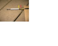
Shift Slide .jpg
My shift slide with outdrive off is only sliding to the yellow arrow in the above picture. Should it slide over that brass fitting to the red arrow?
 
That brass npt should be tightened into the bell housing so only maybe a 1/16 inch gap between housing and back side of hex surface.

Considering you had this issue before cable change......please look at that bushing i referenced.....what will happen if that bushing has moved up the U shaped end of the vertical shift shaft in the bellhousing will be to high and not shift into reverse.....

Let me know what you find.
 
In case CajunDave does not ever get back to complete this post.

If you look at his picture in post 6 you see the threaded section of the cable which threads into the gimbal housing. I heard that he had not tightened the shift cable fully into the bell housing.

This must be threaded almost all the way in so the face of the hex is within 1/16" of the housing.

By not having it tightened all the way he could not move the cable far enough to get reverse engagement.

This limited his reverse cable movement and the shift linkage movement. The cable moves towards the boat when going into reverse and moves towards the drive when going into forward.
 
This has zero to do with your shift resistance issue. I think that you're on the right track and that you will find the culprit.

*****************

The OEM adjustment procedure, and the suggested measurements, are for an average installation by an average person and/or an average mechanic.
The actual goal is to ensure that the lower shift cable sets the Dog Clutch "sliding sleeve" (while in absolute Neutral) centered equally between each driven gear "dog clutch" engagement teeth. In other words...... with all of the shift components in the Neutral position, the sliding sleeve should be positioned at an equal distance from gear engagement.

Here is a simple tried and proven technique that works for both the Merc A drive and the Cobra drive.
This has been geared towards the OMC Cobra drives, however the principle is very similar for the Merc A drives.


The OEM engineers chose an initial cable adjustment dimension for average Joe mechanic and average Joe user. Hence the
initial adjustment "Tool" and the measurements.
This gets us close ONLY.... and perhaps may be subject to further adjustment.


The whole idea is to center the Dog Clutch "sliding sleeve" equally between the two driven gear Dog Teeth while in neutral.
The pre-determined dimension (the tool) gets you close ONLY, since each scenario may be slightly different.


You can either begin with the suggested OEM dimension, or you may want to begin from scratch.... your call:


1. With the drive fully down (to counter gravity against the sliding sleeve), have a helper swing the propeller back and forth (right and left)
quickly, and in an even pattern and rhythm.

2. You will be at the engine with the lower shift cable disconnected at the linkage arm.


3. As you bring the cable towards a FWD gear engagement, note where you just begin to hear the "ratcheting" sound as the sliding sleeve contacts the FWD gear Dog Teeth. Note where the cable is in it's travel, and find a way to mark it.

4. Now move the cable towards a REV gear engagement. The helper will still be swinging the prop back/forth using the same rhythm.
Again, note where you just begin to hear the sliding sleeve contact the REV gear Dog Teeth.
Note once again where the cable is in it's travel, and find a way to mark it.


5. When you divide this cable travel equally, you will have located theoretical Neutral regarding where the sliding sleeve is in relationship to the
two "driven" gears.


6. Now connect your lower shift cable up to the rest of the linkage so that this "Neutral" travel adjustment is maintained.
The spring loaded cam arm will have maintained it's neutral position.

You may find that the new measurement is slightly different from that of the OEM (or Stuart Hastings dimension for the OMC Cobra drives).

None-the-less, the sliding sleeve will now be at center of travel while in Neutral on the splines of the propeller shaft.
Again, this is the goal!


7. Make your Merc SI or your OMC ESA adjustments after first doing the above.
The final Merc SI or the OMC ESA adjustment must be made while on the water as to acquire the necessary prop thrust resistance.


NOTE: this method works well if all is in good condition. If you have a bad cable, bent shifting rod, or any other items that are not working correctly, it will prevent most any method from working as it should.


.
 
Last edited:
This has zero to do with your shift resistance issue. I think that you're on the right track and that you will find the culprit.

*****************

The OEM adjustment procedure, and the suggested measurements, are for an average installation by an average person and/or an average mechanic.
The actual goal is to ensure that the lower shift cable sets the Dog Clutch "sliding sleeve" (while in absolute Neutral) centered equally between each driven gear "dog clutch" engagement teeth. In other words...... with all of the shift components in the Neutral position, the sliding sleeve should be positioned at an equal distance from gear engagement.

Here is a simple tried and proven technique that works for both the Merc A drive and the Cobra drive.
This has been geared towards the OMC Cobra drives, however the principle is very similar for the Merc A drives.


The OEM engineers chose an initial cable adjustment dimension for average Joe mechanic and average Joe user. Hence the
initial adjustment "Tool" and the measurements.
This gets us close ONLY.... and perhaps may be subject to further adjustment.


The whole idea is to center the Dog Clutch "sliding sleeve" equally between the two driven gear Dog Teeth while in neutral.
The pre-determined dimension (the tool) gets you close ONLY, since each scenario may be slightly different.


You can either begin with the suggested OEM dimension, or you may want to begin from scratch.... your call:


1. With the drive fully down (to counter gravity against the sliding sleeve), have a helper swing the propeller back and forth (right and left)
quickly, and in an even pattern and rhythm.

2. You will be at the engine with the lower shift cable disconnected at the linkage arm.


3. As you bring the cable towards a FWD gear engagement, note where you just begin to hear the "ratcheting" sound as the sliding sleeve contacts the FWD gear Dog Teeth. Note where the cable is in it's travel, and find a way to mark it.

4. Now move the cable towards a REV gear engagement. The helper will still be swinging the prop back/forth using the same rhythm.
Again, note where you just begin to hear the sliding sleeve contact the REV gear Dog Teeth.
Note once again where the cable is in it's travel, and find a way to mark it.


5. When you divide this cable travel equally, you will have located theoretical Neutral regarding where the sliding sleeve is in relationship to the
two "driven" gears.


6. Now connect your lower shift cable up to the rest of the linkage so that this "Neutral" travel adjustment is maintained.
The spring loaded cam arm will have maintained it's neutral position.

You may find that the new measurement is slightly different from that of the OEM (or Stuart Hastings dimension for the OMC Cobra drives).

None-the-less, the sliding sleeve will now be at center of travel while in Neutral on the splines of the propeller shaft.
Again, this is the goal!


7. Make your Merc SI or your OMC ESA adjustments after first doing the above.
The final Merc SI or the OMC ESA adjustment must be made while on the water as to acquire the necessary prop thrust resistance.


NOTE: this method works well if all is in good condition. If you have a bad cable, bent shifting rod, or any other items that are not working correctly, it will prevent most any method from working as it should.


.


As I read this closer it would appear you are referring to a shift cable adjustment for a Bravo style drive

As a NON certified mercruiser technician "ever" or in anything Mercruiser I would suggest you do not add to things you have little if any experience in. The procedure I listed is tried and true (thousands of times by me) and is based on the exact procedure in the mecruiser manual Which you obviously don't have.

Do not suggest it is some back yard yahoo set up procedure used by uninformed or uneducated or inexperienced persons.

Parts of your procedure are incorrect to begin with.

The reason for trimming up the drive an inch or two from all the way down is to put a strain on the cable (worst case scenario). If you have ever worked on a mercruiser short shift cable issue you would know this. The cable gains slack when the drive is trimmed up. By doing this you overcome this issue.

Also there is no "TOOL" used on Alpha One Gen I or II!!

As far as the OEM dimensions......Factory short shift cables are CRIMPED at that exact dimension!! So what do you know!

Again...............really????


................................

As I read this closer it would appear you are referring to a shift cable adjustment for a Bravo style drive
Incorrect!
The B drive is a Cone Clutch gear engagement drive that also uses a sliding sleeve. My procedure applies to the dog clutch drives.

As a NON certified mercruiser technician "ever" or in anything Mercruiser I would suggest you do not add to things you have little if any experience in. The procedure I listed is tried and true (thousands of times by me)
Thousands of times???? That is quite a statement! You are aparently much older than what your attitude suggests.

and is based on the exact procedure in the mecruiser manual Which you obviously don't have.
Conjecture!

Do not suggest it is some back yard yahoo set up procedure used by uninformed or uneducated or inexperienced persons.

Parts of your procedure are incorrect to begin with.
Please be more specific!

The reason for trimming up the drive an inch or two from all the way down is to put a strain on the cable (worst case scenario). If you have ever worked on a mercruiser short shift cable issue you would know this. The cable gains slack when the drive is trimmed up. By doing this you overcome this issue.
An inch or two from full down would be just fine.
Perhaps you are missing the point re; gravity against the sliding sleeve if the drive was trimmed up.


Also there is no "TOOL" used on Alpha One Gen I or II!!
Please read it again.
This was first compiled for the OMC Cobra owners, of which there is a special tool for use in the procedure. The "tool" gets you close ONLY!
Both the A drive and the Cobra drive use Dog Clutch gear engagement.
Both use driven gears with Dog Clutch engagement teeth in conjunction with the sliding sleeve that engages in either direction.

As far as the OEM dimensions......Factory short shift cables are CRIMPED at that exact dimension!! So what do you know!
Restricing one's self to thinking "within-the-box" is why the OEM offers a user friendly procedure!
One must be able to occasionally think "out-side-of-the-box".


Once again Jack, your attitude is less than desirable and is very un-becoming of this forum.
You could have easily chosen to (in a gentlemanly and adult like manner) politely explain why you disagree me.
Had you done so, everyone reading this thread would not be shaking their heads in disgust.


Last edited:
IMG_5589.JPG
I would like to thank everyone on here for helping teach my stupid daddy how to get this shifting issue fixed.
The problem was as kghost described. I had an argument with my helper(my wife) while screwing in the brass threaded portion of the shift cable outersheathing that screws into the gimbal housing. We disagreed about her effort in putting tension on the shift cable sheath as I was screwing it in with my ratchet. Anyway, I got sidetracked and never came back to tighten it all the way.

Very kind of everyone to go out of their way to help us out! God bless and if I can ever help anyone with anything to repay their time please don't hesitate to ask. I'm a football coach in South Louisiana so it probably won't be of tremendous help from a boat mechanic advice standpoint, but I feel like I know this shifting system now backwards and forwards.

Thanks again!
 
................................

Again

you are combing two methods (in your own words) whether you think they work for both OMC and Mercruiser is wrong. I have also worked on OMC outdrives and outboards and I am fully aware of there set up procedures. The use of the word tool is wrong as there is no tool for ALPHA and it will only confuse people vs trying to show them how "intelligent" you are, there is a tool for Bravo shift cable set up, a cheap plastic set up tool.

If someone chooses to use the OMC or the method you describe that is fine but my experience says I use the Mercruiser/my method only.

And yes over one thousand times as I said and I actually worked in the industry for many years not at an AUTO PARTS STORE as you have alluded to.!!!!
Two full time mechanics/technicians (me being one of them) 7 days a week during the season (March thru October) for ONE full service and boat sales marina on a large fresh water lake.

RE; I am not missing the point of drive down vs up I know exactly the point as I have dealt with this issue, Again over a thousand times!! Fully down and the cable is fully relaxed, trim it up and it creates slack and a minor amount of strain on the cable so if there are any issues it will show up. END OF STORY!

Here is the deal RICARDO...........Keep your "opinions" to other forums where others may be overwhelmed and in Awe by you apparent knowledge of so many things.

I for one am not!!!

After all this time it is very clear and very apparent you know very little about Mercruiser. If you did you would not interject your unknowledgeable opinions on so many mercruiser topics!

The only disgust is when you post and confuse the crap out of the person needing help.

I am not getting paid here so I don't care if my opinions and writings offend you.

You keep posting CRAP and I will keep hammering you for it!
 
Back
Top