Logo

What is too much play in the driveshaft cone & roller Assembly?

Klink

Regular Contributor
On a 1983 Evinrude 60hp 2 cylinder, what is too much side to side or up and down play (in inches or mm?) on the driveshaft at the cone & roller assembly with the complete water pump and the bearing housing assembly removed? I'm trying to determine if the roller assembly needs replacing it seems to me to have to much side to side movement.
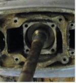
Bearing housing.JPG
 
Last edited:
If it was running and bearing is ok leave it alone. You have to have the driveshaft shimming tool to set it up correctly..
 
I have to agree.------Without the special tool you can not make a decision.----And driveshaft must be removed from lower unit to get the correct shimming.
 
If it was running and bearing is ok leave it alone. You have to have the driveshaft shimming tool to set it up correctly..
I have to agree.------Without the special tool you can not make a decision.----And driveshaft must be removed from lower unit to get the correct shimming.

Will do as both of you advise, thanks for the quick response.

For my education

- the only shims I see on the diagram go between the roller assembly and the bearing housing assembly, is that what we are talking about? I found 2 shims there and one was worn through on one end. Should I just put them back as they are?

- I don't see how one could know what size the shim is unless it has a part number stamped on it (How does one measure .002 - .007!)

- Concerning the shimming tool, I read somewhere that it was like $400, so I can see why it would be out of the question, is this a possible cheap solution?: https://www.youtube.com/watch?v=020F6DfPyog
 
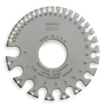
My feeler gauges go down to .005, and these shims are visible thinner. This is the tool that I know off for measuring thin sheet, I have this tool but it only goes down to 36 wire gauge which is like .009 (I have not found where I put it):

Z2_yryfo5oy.JPG
 
Last edited:
I used to work in a shop where measuring to millionths of an inch was done.-------You would use a micrometer to measure the shims.-------If one of the shims was worn out then I would be concerned too.--------So why did you take this apart in the first place ??
 
It is my neighbors motor, I'm doing the work for him and with him to help. It had a bad gear lube leak coming out the top, at the driveshaft seals at the bearing housing. One of the shims is rusted through, has a gap of like 3/16", it is from corrosion, not wear.
 
Last edited:
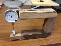
I measure with a depth gage rigged up like a thickness gage and compared it with my feeler gage to double check accuracy and I got .006 for each one.
 
Was there alot of metal shavings in the gearoil? Those shims are for pinion height and proper gearlash. Either its right or it aint. If anything you want it a tad loose if the gears are banging together it will cook the gears in no time at 5000 rpms.
 
Boobie:
I rigged up a thickness gauge like the picture below and measured the shims with it (I had the depth gage already). I checked the thickness gage's accuracy with my feeler gauges. I am confident that they are two shims of .006", so that is what I ordered.

Kimcrwbr1:

When I drained the gear oil all that came out was a little bit black water, and no metal shavings. I think the engine was not used for a long time and the oil drained out slowly, and some water got in through the top seals. The engine would not run the way it was (the carbs, the spark plug wires were backward, and other indications), so that is how I surmise that it sat a long time without use.

I drained it and flushed it with diesel fuel and found no shavings. I then filled it with gear oil so we could test it on the lake and in the process flushed the gear case really well. The engine ran fine. When we brought it back and tilted it, that is when we discovered the big leak out the top, which is where we are today. Again, I did not see any metal shavings.

e1312e2937d23ab4a3a52ccf76a3d404.jpg
 
Last edited:
Put the new shims in, reassemble and fill with new oil and see how it goes. If the water has damaged the gears and bearings, the damage is already done. I wouldn't suggest running it 10 miles offshore till you gain some confidence in it. Catastrophic failure is possible. Your other option is disassemble it and inspect it now.
 
Will do all as advised, thanks guys.

Do I need a press to put in the two top oil retainers, or can I just push them in with a socket or wood dowel and a hammer (delicately of course)?

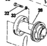
0387067.jpg
 
Last edited:
I just pushed them in, the first which faces down I did with a socket and oak wood dowel and a hammer, the top one which faces up I did with the oak dowel only and hammer (all delicately and even as I went).
 
That should be just fine as long as they press in straight and even. I allways put a light coat of permatex on the outer edge of the seal for giggles. I believe the seals come with a light teflon type paint that does the same thing. A nice flat cut pipe works good also as long as its the right size. Another trick is if there is a groove cut into the shaft from the old seals just dont press them all the way in so the lip of the seal rides on a good surface of the shaft. Just make sure the seal is nice and square with the shaft.
 
Picture in # 19----Can you post one of the bottom of that part ?-------Always pack the cavity between the seals with some grease.
 
That should be just fine as long as they press in straight and even. I always put a light coat of permatex on the outer edge of the seal for giggles. I believe the seals come with a light teflon type paint that does the same thing. A nice flat cut pipe works good also as long as its the right size. Another trick is if there is a groove cut into the shaft from the old seals just dont press them all the way in so the lip of the seal rides on a good surface of the shaft. Just make sure the seal is nice and square with the shaft.

Thanks for the advise, will note it for next time.

I used grease in the cavity and on the outer and inner edge seal.

Regarding the shaft groove it looks good. We drove one all the way down and the top one not quite.
 
Picture in # 19----Can you post one of the bottom of that part ?-------Always pack the cavity between the seals with some grease.

It's already installed. The picture I posted is from Marineengine.com

We did place the seals as per the diagram, back to back, with the lips facing in and out.
 
We got it all done, and got lucky, the only other leak was in the tiny little o-rings #33 that seal the bearing housing screws #32, easy to replace without having to remove the bearing housing assembly #28. My thanks to everyone that assisted here.

Bearing housing assembly.JPG
 
Keep an eye on it for the first few times out. Run it hard and then let sit for a day in the running position. Pull the lower drain plug for a second or two and look for water and metal fragments. If it looks good I keep a oil can full of gearoil and just top it off in the upper vent plug just slowly squirt it in until it takes no more.
 
Back
Top