Logo

SBC 5.7 cam bearings

JV Sr.

New member
In the process of building my GM 350's to 383's I took the engine blocks to the machine shop for boring, decking, clearance for stroker cranks and hot tankings. They installed new cam bearings and when I picked up the blocks yesterday they mentioned that the reverse rotation motor had the cam bearings installed "so they are clocked correctly for a reverse rotation engine". Is this correct? Do reverse rotation engines have their cam bearings installed differently then standard rotation engines?
 
I can assure you, both engines (2005 Carbureted 5.7L Classics) have the same timing chain, crankshaft, oil pump and distributor (but a different drive gear). The camshaft is rotated in reverse and ground for reverse rotation. I've crossed reference the parts used in both engines and the only difference I find is the rear main seal (1 pc rear main), camshaft and distributor drive gear. There are obvious differences with various external parts but the base engines are virtually identical. I'm just concerned that the cam bearings may or may not be installed correctly.
 
Last edited:
I can assure you, both engines (2005 Carbureted 5.7L Classics) have the same timing chain, crankshaft, oil pump and distributor (but a different drive gear). The camshaft is rotated in reverse and ground for reverse rotation. I've crossed reference the parts used in both engines and the only difference I find is the rear main seal (1 pc rear main), camshaft and distributor drive gear. There are obvious differences with various external parts but the base engines are virtually identical. I'm just concerned that the cam bearings may or may not be installed correctly.

JV .... that is correct!
Just make sure that your RH REV Rotation engine camshaft is correct for a chain/sprocket drive, and not for a twin gear drive.
Only when we get into twin gear driven camshafts (for a RH REV Rotation) will the bearings be std rotation.

With a REV Rotation engine, the camshaft "drive" gear will be cut differently (oposite), and will rotate the distributor and oil pump in the Std Rotation direction.
The distributor "driven" gear will also be cut oposite.

Make sure that the distributor is correct for the NOW down-ward force that is created by this gear.


.
 
Also..... when building a 6.3L SBC (383), you should get as far away from the GM full dished pistons as you can.
Instead, build these using a LCQ style piston, and rid yourself of detonation potential and give these babies some real torque!


.
 
bearings are pressed in. it doe"s not matter the direction the engine spins

This is most likely why JV's machine shop informed him of the camshaft bearings.

Technical Bulletin
AERA/AERSCO (American Engine Rebuilders Association)
AERA Technical Services Departmart

July 2002 TB 1996
Optimum Placement Of Camshaft Bearing
Oil Feed Hole Location
The AERA Technical Committee offers the following important information on optimum placement of camshaft bearing oil feed hole location during installation.
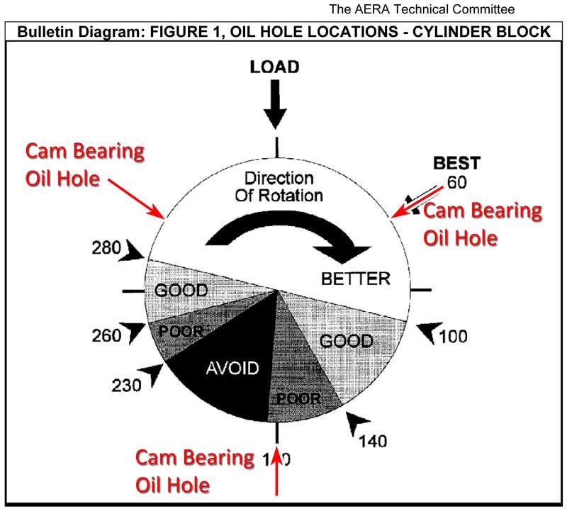
This information should be considered any time camshaft bearing replacement is being done. Maximum camshaft support will be realized by installing the cam bearing oil feed hole to the optimum clock location. Blocks and heads using a 360° oil groove located behind the bearing oil feed, allow one to move the clock position of the cam bearing oil feed hole. This way you can adjust the clock position during cam bearing installation to make sure that the optimum location for the best hydrodynamic wedge is selected. Locating and installing the cam bearing to take advantage of this hydrodynamic wedge will supply the maximum support for the camshaft during engine operation. The direction of camshaft rotation and the engine oil entry point into the bearing control the placement of the hydrodynamic wedge.
Note: If the oil feed passage in the block or head is just a hole without a 360° groove, the bearing oil hole must line up with the oil feed passage in the block or head. In some instances, the bearing oil feed hole in the cam bearing also lines up with a groove cut in the camshaft journal. In those instances, the location of the bearing oil feed hole in the bearing is also very critical fore and aft and may not match up 100% with the hole in the block or head.

The illustration in Figure 1 below shows the optimum engine oil feed hole location for a camshaft that is turning clockwise as viewed from the front of the engine.

CamBearingClockPositionDiagram.jpg


Note: If the camshaft being used is driven with a gear-to-gear arrangement, or is a reverse rotation engine with a chain drive, the cam bearing oil feed hole will require
repositioning to the opposite lower side. This is due to the fact that the camshaft is turning in the opposite direction as noted above.


Also..... when building a 6.3L SBC (383), you should get as far away from the GM full dished pistons as you can.
Instead, build these using a LCQ style piston, and rid yourself of detonation potential and give these babies some real torque! .

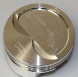
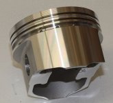
You are totally correct here, my piston choice are these. Wiseco piston.jpgWiseco 1.jpg And using 64cc Vortec heads giving me a quench of .042.
 
You are totally correct here, my piston choice are these.

View attachment 14429View attachment 14430

And using 64cc Vortec heads giving me a quench of .042.

While the cylinder head combustion chamber volume will certainly be part of equation for determining the Piston Dish Volume, and eventual SC/R, it does not affect or determine the quench dimension.

The quench dimension formula is ..... Piston deck height + compressed head gasket thickness.

With regard to a 3.750" stroke 6.3L SBC, the Hot Rod guys shoot for a quench dimension of approx .060" .......... but your .042" is very close for a Marine Cruiser build.
If you do a Closed Cooling System, you can use the high grade Automotive head gaskets that will give you more options for compressed thickness.


Also, while the Hot Rod guys love the 6.0" connecting rods ..... for a 6.3L Marine Cruiser build, you'll do better if you were to stick with the 5.7" connecting rods.
This wrist pin location leaves the skirts longer.
 
While the cylinder head combustion chamber volume will certainly be part of equation for determining the Piston Dish Volume, and eventual SC/R, it does not affect or determine the quench dimension.

The quench dimension formula is ..... Piston deck height + compressed head gasket thickness.
Deck height is "0" and a .042 compressed head gasket is used for my .042 quench.
With regard to a 3.750" stroke 6.3L SBC, the Hot Rod guys shoot for a quench dimension of approx .060" .......... but your .042" is very close for a Marine Cruiser build.
If you do a Closed Cooling System, you can use the high grade Automotive head gaskets that will give you more options for compressed thickness.
Engines will run a half closed cooling system, as I want the exhaust manifolds to be raw water cooled to help pull heat out from the heads.

Also, while the Hot Rod guys love the 6.0" connecting rods ..... for a 6.3L Marine Cruiser build, you'll do better if you were to stick with the 5.7" connecting rods.
This wrist pin location leaves the skirts longer.
5.7" PM rods used

I have read and reread about everything I could find on a quench build engine including Dennis Moore's book SBC Marine Performance.
 
Back
Top