Logo

Part numbers needed aq131 SP Drive

F5guy

Contributing Member
Finally got around to taking apart to replace corroded filler neck and think I should replace the bellows and 2 O-rings before putting it back together. Anyone know the part numbers or have a diagram they'd share with me is much appreciated. SP CD /SP A1 drive I have serial numbers if it helps.
 
Wow thank you for your help U joins look fine but so easy to change I'll probably just go ahead and order. No clue on the bearing but I'll take a look at that too.

thanks to your help I also found this http://www.volvopentastore.com/Uppe...on_id.562648097--store_id.366--view_id.767490

and think the parts I need are #10 and #54. The bellows is the only part number that matches up with what you sent previously.

925259
125017
876294
Do you know how old the PDS bearing and U-joints are? Now would be the time while the bellows is off.
http://www.volvopentastore.com/Conn...on_id.469438144--store_id.366--view_id.782434
your motor has the hydraulic trim tilt correct?
 
Thanks again for your help hopefully by mid week we'll be be cooling again and ready for a fall cruise before winterizing.

Wow thank you for your help U joins look fine but so easy to change I'll probably just go ahead and order. No clue on the bearing but I'll take a look at that too.

thanks to your help I also found this http://www.volvopentastore.com/Uppe...on_id.562648097--store_id.366--view_id.767490

and think the parts I need are #10 and #54. The bellows is the only part number that matches up with what you sent previously.
 
And why are you taking the upper gearbox apart? The two orings I give you part numbers go between the upper gearbox and the intermediate housing.
 
you are correct sir I was puzzled because the one large o-ring wasn't in the schematic so i tried to make sense of it. Those part numbers you gave me were 100%.
I'm anxious to get this back together and see if it cools properly. Thanks again

The oil drain back tube O-ring is shown in one schematic...... and the larger bearing retainer O-ring is shown in another schematic.
That can be a problem if you are new to AQ series Volvo Penta.


Make certain that the shims underneath the transmission are correct, and that none have become lost!
The goal is a .003" squeeze on the lower "driven gear" bearing when the transmission is fully tightened into position.
In other words...... when the two cases are fully mated (zero gap) , the shim pack will provide .003" presssure against the bearing.


.
 
Last edited:
That's what was driving me nuts until I figured it out. You obviously know your way around these too bad you're 3k miles away. I'm determined to keep this thing going I call it my James Bond boat. Wellcraft excel.

The oil drain back tube O-ring is shown in one schematic...... and the larger bearing retainer O-ring is shown in another schematic.
That can be a problem if you are new to AQ series Volvo Penta.


Make certain that the shims underneath the transmission are correct, and that none have become lost!
The goal is a .003" squeeze on the lower "driven gear" bearing when the transmission is fully tightened into position.
In other words...... when the two cases are fully mated (zero gap) , the shim pack will provide .003" presssure against the bearing.


.
 
Got it all back together tonight with he help of a great mechanic so wish us luck. Ant wait to fire up. Another question for those in the know. The fluid in the reservoir for the motor that moves tilt up and down. Can I just use transmission fluid or does it take something special. No mention in manual. Thanks.
 
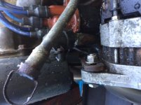
Ok let's forget about the pump fluid for a moment. Got everything back together and it's drawing water on muffs but leaking where copper connects to raw water filter housing. Can you tell me what type of connection this is? Photo attached. IMG_6033.jpg
 
That is just a square o-ring pressure fitting your probably best getting both kinds of rubber seals the two slotted ones for the raw water pump and the square ones you just press in. I order extra to have on hand they are cheap.
 
Was going to edit my last post but don't see that option. Here is where I stand when I removed the pipe there were 2 seals in there so I put back together with one new one as the diagram shows and it leaked. Took apart and installed 2 seals. I made sure it went all the way up both times and it ran without leaking for about 20-30 sec and popped out. I reinstalled 3-4 more times just to make sure it was seated properly and the same thing happens. Surprising to me there is no mechanical joint there. Does this mean something clogged further down the line? Thanks
 
The raw water should flow free through the heat exchanger and then through the exhaust manifold and out the drive. pull the strainer and then pour a gallon of water in the raw water side of the heat exchanger the water should run right out of the drive fairly quick. How old is the exhaust manifold?
 
Ok so water is not free flowing through raw water strainer, fills right up. Next logical step is appreciated ? I'm pretty handy with tools but no experience with marine. I'm assuming I have to figure out if the clog is in exchanger or exhaust manifold. Please let me know next logical step. Thank you
 
Pull the tube from the bottom back of the manifold and pull it out of the heat exchanger and start the motor and see if pressure still builds in the exchanger? it should gush out where the tube was.
 
Pulled tube from bottom of exchanger and it's free flowing from the strainer to bottom. Looks like exhaust manifold is clogged, worth trying to blow out or just need to replace. Thanks in advance.
 
I would pull the manifold and look at it first. You may be able to rod out the slotted ports coming out for better water flow. Also look at the baffle cast into the large hole that separates the port in half. If there is a hole in the baffle the manifold needs replaced. hook the water tube to the manifold and connect it to the garden hose and see how well water flows out the four slots around the large exhaust port. When I first got my AQ131 I pulled the manifold and chipped the rust out of the four slots and it worked real good until I forgot to drain the manifold two winters ago and it froze up and cracked all along the lower part of the manifold. You can get new gaskets just use the B230 gaskets at any auto parts store.
http://www.ebay.com/itm/Volvo-Exhau...ash=item2a6d8ff777:g:gEkAAOSwCfdXpKZt&vxp=mtr
 
Well this just got more interesting. Got all the bolts out of the manifold easily except one. Head snapped off and manifold won't come off over it. I'm guessing I have to try and cut it between the block and manifold unless anyone has any other ideas. I'll try to slip a hacksaw blade down there and hope I don't mess anything off. I'm open to all advice or opinions, thanks in advance.
 
Or I can try some wooden wedges or maybe just smash the manifold with a big ole hammer (if it's cast). I'm even toying with removing the head but that overhead can makes it complicated for me. Someone please pipe in before I make a mistake. It's getting cold and I'd really like to get this back together before we have freezing temps.
 
Back
Top