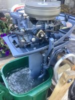
1968 6hp Johnson CD-25A cooling system water flows
I could not find a water flow diagram that really shows the water as it flows through the engine, other than an undetailed drawing in the service manual (see it below), therefore I decided to post here the water flows as I saw it from disassembling the cylinder head and the thermostat cover. I'd like for others more experienced than I to confirm if I am correct.
From what I could see, I surmise that the water
1) Continuously comes in through the main water flow shown below on the engine block, then goes into the thermostat housing hole at the top then down the tube hole on the other end of the thermostat housing and out the exhaust. There is a restriction in the thermostat housing cap, so that the other continuous flow hole #2 below, receives more water pressure.
2) Water also continuously flows to the cylinders through the engine block water outlet at 7 o’clock on the top cylinder. That water fills up the cylinder and can only enter the cylinder head by the 3 small holes and the one bigger hole at 2:30 o’clock on the top cylinder. The large rectangular exhaust hole at 6 o’clock of the bottom cylinder, must have a restriction so that the cylinders do fill up with water before exiting. The big exhaust hole at 5 o’clock of the bottom cylinder is for the cylinder head water to exit to exhaust.
3) The thermostat housing cup that houses the thermostat, has two holes that allow additional water to exit and cool the engine, when the thermostat opens. Until the thermostat opens, the cup fills with water from below from the water coming from the water outlet at 7 o’clock of the top cylinder. When the water heats up, the thermostat opens. (I surmise it is this way, because the thermostat mechanism is below in the cup, and not above it, so there has to be water below to expand the thermostat). Once the thermostat opens, it increases the flow of water to cool the engine. (QUESTION – why would the water not flow down when the thermostat opens, rather than flow out the top and into the tube? ANSWER - According to the service manual diagram, it flows up and out to the exhaust)


.jpg")


I could not find a water flow diagram that really shows the water as it flows through the engine, other than an undetailed drawing in the service manual (see it below), therefore I decided to post here the water flows as I saw it from disassembling the cylinder head and the thermostat cover. I'd like for others more experienced than I to confirm if I am correct.
From what I could see, I surmise that the water
1) Continuously comes in through the main water flow shown below on the engine block, then goes into the thermostat housing hole at the top then down the tube hole on the other end of the thermostat housing and out the exhaust. There is a restriction in the thermostat housing cap, so that the other continuous flow hole #2 below, receives more water pressure.
2) Water also continuously flows to the cylinders through the engine block water outlet at 7 o’clock on the top cylinder. That water fills up the cylinder and can only enter the cylinder head by the 3 small holes and the one bigger hole at 2:30 o’clock on the top cylinder. The large rectangular exhaust hole at 6 o’clock of the bottom cylinder, must have a restriction so that the cylinders do fill up with water before exiting. The big exhaust hole at 5 o’clock of the bottom cylinder is for the cylinder head water to exit to exhaust.
3) The thermostat housing cup that houses the thermostat, has two holes that allow additional water to exit and cool the engine, when the thermostat opens. Until the thermostat opens, the cup fills with water from below from the water coming from the water outlet at 7 o’clock of the top cylinder. When the water heats up, the thermostat opens. (I surmise it is this way, because the thermostat mechanism is below in the cup, and not above it, so there has to be water below to expand the thermostat). Once the thermostat opens, it increases the flow of water to cool the engine. (QUESTION – why would the water not flow down when the thermostat opens, rather than flow out the top and into the tube? ANSWER - According to the service manual diagram, it flows up and out to the exhaust)
Last edited: