Logo

76 johnson ignition/key switch wiring helppppp

pilgor

New member
hi there
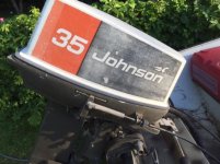
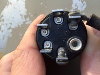
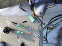
i need help wiring an ignition/key switch for a 76 johnson outboard motor(think its 76??). motor is hooked up to steering wheel and throttle so there are 2 black wires from the throttle. the rest are from the motor itself. the switch is a 6 terminal push to choke. ill post pics so you guys can get a better understanding. one blue wire has with line on it.
thanks
 

Attachments

  • image1.jpg
    image1.jpg
    47.3 KB · Views: 1,962
  • image2.JPG
    image2.JPG
    80.5 KB · Views: 3,690
  • image3.jpg
    image3.jpg
    40.8 KB · Views: 1,655
Normally the colors (wires) and the marked terminals of the switch are:

Black/Yellow = Raised "M" terminal (Kill Circuit)
Black = Regular "M" terminal (Ground)
Purple/White = "C" terminal (Choke or fuel primer solenoid)
Purple = "A" terminal (Accessory)
White = "S" terminal (Starter Solenoid)
Red = "B" terminal (12v source)

If your wiring is different....explain.
 
The blue/white and blue wires go to the M terminals it dont matter which ones. Do not apply battery pos to either wire for even a second you will need new coil/s. To kill the motor your just shorting the two sets of points together under the flywheel. Red/purple is battery, white is start and purple is choke.
 
What is the model number of the motor? The two black wires to the controls is the neutral start safety switch more than likely you need to confirm the model number before connecting the battery. In 1977 they went to a CD type ignition so ID is real important.
 
Last edited:
hi there thanks for the responses,
1. wire colours are: red w/white stripe, purple with white stripe, white, blue and then blue w/white stripe. those come from the motor. the two solid black wires come from the throttle.
2. shorting the 2 blues wires under the flywheel? think purple w/white is choke no?
3. model number is 35e766

thanks
 
How old are the points? That is the correct wiring purple/white is the choke my diagram shows red/purple for battery pos purple possibly just faded. The model number is probably 35E76G. Once running check the timing with a timing light. On the outer edge of the points plate are two marks and a single line on the flywheel. The flywheel mark needs to be inbetween the two marks on the plate at idle speed. If not do the engine a favor and replace the points and condensers. Without having the special tool preset the points at exactly .022 then check it when running with a timing light.
 
I answered the question on the other forum where you asked it. Yes, that is a 1976. And yes the kill wires are blue and blue/white and go to the "M" terminals. The black ones are not original to the ignition switch. Please explain how they are connected to the throttle.
 
Do you have pics of the controls? The only thing I can think of is a neutral start switch. One should go to ground and the other to the start solenoid on one of the small terminals?
 
The points? The switch is brand new and re did the ends of the wires. As for the controls it's just a basic throttle 2 wires into it. When I took out old switch out one black was connected to the white wire and the other to the s on switch. The old switch had a toggle switch which the choke was connected to. So I got rid of toggle for a push to choke switch. I'm sorry don't have a pic of controls right now(at work). As for the flywheel the motor purred like a kitten last yr. just misplaced the key, and had to choke motor out to kill engine. So something with a ground may be missing. Thanks guys
 
It definately sounds like the start safety switch from the controls is being used. Originally the safety switch is in the motor on the starboard bracket it provided ground to the coil on the start solenoid. It must be in neutral for the starter to work. Your motor has points under the flywheel do you have a timing light? Ignition timing is on point gap the best way to check it is with a timing light. As the points burn up it changes ignition timing.
http://www.maxrules.com/graphics/omc/wiring/18-25_EL-START_TO_1972.jpg
This is basically your ignition wiring the black wires are the same as the blue ones. Note the start circuit you want to hook the black wires to the controls to the S terminal on the key and black to white is correct, then look at the start solenoid one of the small terminals needs to be going to engine ground.
 
The graphic below is an actual scan from the OMC 1976 35hp wiring diagram. You can see that it shows different colors than what you describe. However, since you have upgraded to the six (6) terminal "push to choke" ignition switch.... the wire color to switch terminal setup that you have would be as follows.

"B" = Red/White = (Battery Voltage)
"C" = Purple/White = (Choke)
"S" = White = (Starter Solenoid)
"M" = Blue = (Either Point Set)
"M" = Blue/White (Other Point Set)
"A" = Anything you want voltage applied to when the key is in the ON position. Caution here..... A high ampere drain could blow the power fuse located at the engine.

76_35hp_Wiring-3.jpg

If you would like the complete 1976 35hp wiring diagram, reply with your email address and I'll get it to you.
 
Last edited by a moderator:
Back
Top