Logo

I could use some help on a Honda BF150, MIL blink code = 41; A/F Sensor Related Issue

dhicks

New member
2008 Honda BF150MIL blink code = 41


From the shop manual, that means one of these is the problem:
- Open or short circuit in the A/F sensor heater wire
- Faulty A/F sensor heater
- Faulty ECM


I don't have the HDS tester or the test harness.


I've reset the malfunction indicator three times. But whenever I turn the motor on, 60 seconds later the malfunction beeper goes off. The A/F sensor is new. I'd installed a used one before I bought the new one and it did the same thing, so I took a chance and ordered a new one.


My shop manual is missing chapter 5 page 44, which contains the testing information. There is a chapter 5 page 90+ that goes through the troubleshooting steps but that section requires a test harness.


Can I get some help with going through the diagnostic process?
 
I don't have the manual for this so I can't provide you with the requested "steps". But, I do have extensive background with fuel injection engines.
Here's what I would do:
Your code is directing you to the heater circuit. The sensor has been changed twice with the same results so we can assume the heater is good, That leaves the wiring.
You need to unplug the wire to the heater FROM THE ECM and from the sensor. DO NOT USE AN OHMMETER to test this wire! You need to LOAD TEST the wire to obtain an accurate finding. The ohmmeter will likely tell you the wire has continuity. You can do a quick check to see if it is completely open but if it shows continuity you need to proceed with the load test.

It's simple. rig up an old sealed beam type headlamp so that you can use jumper wires to power it with a 12v battery. Observe how bright the light is with your jumper wires. Then, introduce the heater circuit wire into the circuit to power the bulb. It MUST shine with the same intensity or the heater wire is damaged. While powering the lamp this way you can also wiggle test the wire to see if the lamp dims or goes out. This is an excellent way of finding EXACTLY where the wire is bad.
Also, keep in mind that the problem may not be the wire but in the ENDS of the wire or the connector socket for the sensor or the ECM.

If this doesn't make ANY sense to you then you should probably not try it. But, if you have a bit of background with 12v electrical this should help you pinpoint the problem.

Good luck.
 
One other thing to check is the A/F relay.

It should be located in the fuse box area.

If you post your serial number, I can be more specific as to where it is located.

In the more current 150's....they have 4 relays in the fuse box area. Main, start, fuel and AF.

There is also a fuse that supplies the power through the relay to a/f sensor..... a 30 amp fuse. It might be blown. Of course, it could be blown from a faulty relay or a short in the wiring to the a/f sensor. It could just be corroded relay terminals.

It may be a chicken or the egg situation....

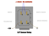
If you find the relay, you can check its operation by applying 12v to terminal 3 and ground to terminal 4. If you put an ohm meter across terminals 1 and 2, you should have continuity with power applied to terminals 3 and 4. When you take the power off, the meter should read an open circuit across terminals 1 and 2.

Without a relay in front of me, I am not sure if the terminals are marked.

Mike
 
jgmo -- I was looking at the service manual and it says there should be 2-3 ohms between the two black wires on the sensor itself. I checked the original sensor and it was an open circuit (definitely bad). When I checked the new sensor it read just 1.1 ohms. Does that raise reg flag or should I proceed with the load testing?

hondadude -- It's a 2008 BF150, model number
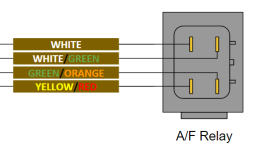
BF150AK0XA, serial number BANJ-1300970. I checked all of the fuses and they are okay. The terminals aren't marked, but I've attached a simple diagram showing the connections/wires on mine.

Capture.PNG
 
Yours should be located on the right side of the fuse box.
The white and white/green should be terminals 1 and 2. The yellow/red should be terminal 3 and green/orange terminal 4.

Your service manual should have a couple of pages of tests for the a/f relay. It shows how to test at the a/f sensor connector.

By the way, a 10 amp fuse feeds the voltage that goes through the relay to the a/f sensor.

Mike
 
The service manual I have is a PDF and the page(s) that goes through the steps for testing this are blank. Regardless, using the information you provided I tested the relay. Assuming I did everything correctly, the relay is bad. No clicking in the relay, no continuity across terminals 1 & 2.

Air Fuel Ratio Sensor Relay.png (corrected illustration)
 
Last edited:
Good deal. You probably have already found the part number. However, it looks like it is 38543-ZY6-003.

Hope that takes care of your problem.

Mike
 
Back
Top