Logo

OMC Controller Plug

echoffmfann

New member
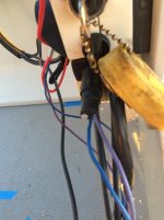
I have a 1990's Johnson 90HP VRO motor and the sidemount OMC controller. We had to move everything to a different boat and I can't recall where the purple and Blue wire go from the controller? It's a 3-pin connector but only has those two wires. I THINK it's for a tach, but all reading points to a purple/grey/black combo. Can anyone confirm where the wires in this photo go (Blue and Purple)?
 

Attachments

  • wires.jpg
    wires.jpg
    55.7 KB · Views: 18
I had the same problem with wires when I replaced my key switch as it was slightly different than the one I removed so i did a search for OMC wiring diagrams and up popped several sites one of which was "images" and with loads to choose from I selected the one for my circuit, printed it off and went down to the boat and completed the installation in a few minutes. I do know that the black is ground (- Neg)
 
Your engine may or may not follow these standards. Most do. (Hope this comes through...

The current ABYC Recommended Colors

Color Where Used / Function
Yellow/Red= Starting Circuits
Brown/Yellow or Yellow= Bilge Blowers
Dark Grey= Navigation Lights & Tach Signals
Orange= Accessory Feeds
Brown= Pumps
Purple= Instrument Feeds
Dark Blue= Cabin and instrument Lights
Light Blue= Oil Pressure
Tan= Water Temperature
Pink= Fuel Gauge Sender
 
Last edited:
Back
Top