Logo

Installing a lighting stator and recharge system on 1975 Mercury 110 9.8 HP...

Jason Robo

New member
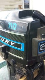
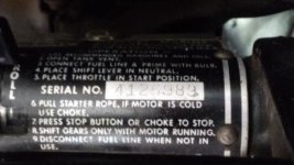
Hey guys! So I have a 1975 Mercury 110 9.8 HP (serial 4126989)that i'm trying to install a lighting stator on and having some difficulty with doing so.

The lighting stator I have purchased is PN 74367A12.I removed the housing and flywheel last night, and reallycouldn'tfigure out where it mounts under the flywheel with the ignition stator.

Is there something Im not seeing or don'tknow about when installing this? It doesn't seam to fit under the flywheel with the ignition stator installed.

Another thought... Do I even need this part to charge my batteries and power my lights? Or do I just need to wire up the existing ignition stator to my electrical system?

Also, I am wanting to install an electric start system too, and think I have purchased the wrong starter housing for the motor.

I have already purchased numerous parts to accomplish this and its not adding up, so if you guys could tell me what the correct part numbers are, that would be a great help also.

The parts I have purchased so far:
Lighting Stator 74367A12
Starter Housing
91871A1 (which I found does not fit correctly)
CDI Voltage Regulating Rectifier
585114 193-5114
Starter motor 50-73531
Electric Start Flywheel 1 - 6105A9

Any and all help would be greatly appreciated!

Thank you!
:cool:
 
The "lighting stator" kits were not designed for "charging a battery", that was a different kit (just wanted to get that out front).

The lighting stator in conjunction with the lighting regulator will produce 12'ish volts which you wire directly to your nav lights (can't use it for a stereo, gps or the like) - whenever the motor is running you have "nav lights" - the package was designed exactly for that "so you don't have to have a battery on board to power the nav lights" - I run one on my 15 horse.

At idle/low rpms you get a dim glow out of your lights (which is why you can't use it to power accessories), throttle up a bit (2000'ish rpms) and your lights are running at full brightness.

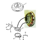
The lighting stator mounts right on (top) of the regular stator (there is a "terminal block" on the off side of the stator - you get rid of that when adding the other "stator" - when you look at the stator it kinda looks like a "half unit" - the lighting stator mounts on the (bare side) - if I'm making sense here. There should be a good set of instructions that came with the kit. (I have cobbled a diagram below)

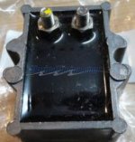
Re-reading your post it looks like you are trying to "piece meal" the kit together. From you list of parts the CDI voltage regulator doesn't look like anything that would have joined up to "this stator" - the OEM part is long discontinued and don't know if this part you have which is NOT a replacement for merc part 95845T (which goes with the lighting stator) will work or not.

This site (marineengine.com) does have some existing stock of the correct part. (pic below)

Anyhow, here's the diagram and what the regulator should look like:

lighting stator.jpgvoltage regulator.jpg
 
The "lighting stator" kits were not designed for "charging a battery", that was a different kit (just wanted to get that out front).

The lighting stator in conjunction with the lighting regulator will produce 12'ish volts which you wire directly to your nav lights (can't use it for a stereo, gps or the like) - whenever the motor is running you have "nav lights" - the package was designed exactly for that "so you don't have to have a battery on board to power the nav lights" - I run one on my 15 horse.

At idle/low rpms you get a dim glow out of your lights (which is why you can't use it to power accessories), throttle up a bit (2000'ish rpms) and your lights are running at full brightness.

The lighting stator mounts right on (top) of the regular stator (there is a "terminal block" on the off side of the stator - you get rid of that when adding the other "stator" - when you look at the stator it kinda looks like a "half unit" - the lighting stator mounts on the (bare side) - if I'm making sense here. There should be a good set of instructions that came with the kit. (I have cobbled a diagram below)

Re-reading your post it looks like you are trying to "piece meal" the kit together. From you list of parts the CDI voltage regulator doesn't look like anything that would have joined up to "this stator" - the OEM part is long discontinued and don't know if this part you have which is NOT a replacement for merc part 95845T (which goes with the lighting stator) will work or not.

This site (marineengine.com) does have some existing stock of the correct part. (pic below)

Anyhow, here's the diagram and what the regulator should look like:

View attachment 13106View attachment 13107


First of all, thank you both for responding so fast! I really appreciate it!

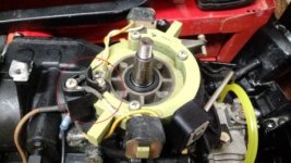
So if I understand you correctly, I have to remove this (circled in red), and put the lighting stator in its place?

IGNITION STATOR.jpg

And if so, where do I terminate the wires that are attached to the terminal?

And yes, you are correct, I am piecing this all together on my own. I am trying to add the lighting stator, the battery recharge function, and also electric start. Can you tell me if I have the correct parts?

Do I need to get any more parts to achieve this?

The starter housing concerns me in the sense that, the screws match up on the left and right side of the powerhead, but the rear screw hole does not. The hole on the housing sits further back than the actual hole. Was there a bracket that mounts to the powerhead, and then to the housing to secure it?

Also, in what I am trying to do, wouldnt I need the CDI rectifier to regulate the voltage.

Please forgive me for my ignorance, I am new to working on outboard electrical systems.

Thank you so much for all your help!

IGNITION STATOR.jpgMerc 110 pic.jpgMerc 110 Serial.jpg
 
Last edited:
I always admire a project person but if it was me I would carry an extra battery to feed lights or other stuff and forget this one...to convert to electric start on this motor will be a project in itself..finding parts etc...and you don't need it if this motor is running right...a motor charging system,especially on a motor this size, charges so slow its almost useless...

after having said that I wish you luck...
 
Hahaha! Yes, I do like projects sir! I believe I have most of the parts needed snd I just found out that I need a couple more which I have already found online...

Other than that, I just need to figure out how to hook it all up!

To me it is worth it because this motor runs great, and has EXTREMELY low hours... its practically brand new!

Thank you!
 
Understand that that coil is tiny--more like a trickle charger--so don't expect it to keep up with, say, running an electric trolling motor.

Jeff
 
Well Jeff, the idea is to have a trolling motor, a single battery, and the motor with electric start, the lighting stator powering the lights, the recharge system charging the battery while under way, from using the starter and the electronics onboard while the outboard isn't running.

Is there a problem with this idea that Im not seeing?

Thank you!
 
Also, do I need both the lighting stator for the lights, AND the recharge system as well? or are they the same thing? Im confused by this...

Thanks in advance!
 
So, I will try and unravel this a little bit.

The "lighting stator" that you are going to add under the flywheel can be used to power a "lighting regulator" OR a "rectifier" but not both - it was initially designed for the lighting regulator.

If you connect the leads to a lighting regulator it will "directly power" your nav lights - the lighting regulator is not designed to charge a battery and would likely do an extremely poor job of trying to charge a battery.

If you connect the leads to a "rectifier" (standard diamond shaped Merc rectifier used on numerous models) you will get a "charge function", but as Jeff notes, it's barely more than a trickle charge. I'm thinking at max rpms it's barely making 3 amps (trickle charger is about 2 amps in comparison). So while it will keep a "fully charged battery topped up" (replace the discharge from using an electric start, or running the lights for an hour or two), as noted, it will not "replenish" a heavily discharged battery.

If you consider a group 24 marine battery (so the smaller ones) "packs in" 70-85 amp hours depending on brand, if it was 50% discharged you would have to run at "full throttle" for minimally 12 hours to "recharge" the battery - so just not practical in any kind of application.

Getting back on track here - if you go the "charge route" then you will connect to a battery (and must always be connected or you will fry the rectifier and possibly the charge/lighting stator) and then run your nav lights, starter and whatever else "from the battery".

If you choose to stay with the manual start and simply add the "lighting regulator", you could power your lights directly from the lighting regulator and NOT have to lug around a battery.

You could go with a 3rd option, that would be use the lighting regulator to power the lights and use a battery "not being charged by the motor" to power your electric start - the battery would be charged by a trickle charger/on-board 120V charger "while you are at the dock or on the trailer in the driveway".

That might sound "uncommon/different", but that is exactly what I do with my late 1950's 40 horse Gale. It has an electric start but there was never an allowance for "recharge capability from the motor" so I simply mounted a trickle charger on the inside of the transom and I plug it in when I'm on shore - given the very limited charge you would get from the system you are looking at installing, you wouldn't gain any significant benefit from going with the charging system in most cases - however, depending on how you use the boat, it still might be desirable (go into an isolated back lake for a week at a time with no "shore power" available).
 
Last edited:
So, I will try and unravel this a little bit.

The "lighting stator" that you are going to add under the flywheel can be used to power a "lighting regulator" OR a "rectifier" but not both - it was initially designed for the lighting regulator.

If you connect the leads to a lighting regulator it will "directly power" your nav lights - the lighting regulator is not designed to charge a battery and would likely do an extremely poor job of trying to charge a battery.

If you connect the leads to a "rectifier" (standard diamond shaped Merc rectifier used on numerous models) you will get a "charge function", but as Jeff notes, it's barely more than a trickle charge. I'm thinking at max rpms it's barely making 3 amps (trickle charger is about 2 amps in comparison). So while it will keep a "fully charged battery topped up" (replace the discharge from using an electric start, or running the lights for an hour or two), as noted, it will not "replenish" a heavily discharged battery.

If you consider a group 24 marine battery (so the smaller ones) "packs in" 70-85 amp hours depending on brand, if it was 50% discharged you would have to run at "full throttle" for minimally 12 hours to "recharge" the battery - so just not practical in any kind of application.

Getting back on track here - if you go the "charge route" then you will connect to a battery (and must always be connected or you will fry the rectifier and possibly the charge/lighting stator) and then run your nav lights, starter and whatever else "from the battery".

If you choose to stay with the manual start and simply add the "lighting regulator", you could power your lights directly from the lighting regulator and NOT have to lug around a battery.

You could go with a 3rd option, that would be use the lighting regulator to power the lights and use a battery "not being charged by the motor" to power your electric start - the battery would be charged by a trickle charger/on-board 120V charger "while you are at the dock or on the trailer in the driveway".

That might sound "uncommon/different", but that is exactly what I do with my late 1950's 40 horse Gale. It has an electric start but there was never an allowance for "recharge capability from the motor" so I simply mounted a trickle charger on the inside of the transom and I plug it in when I'm on shore - given the very limited charge you would get from the system you are looking at installing, you wouldn't gain any significant benefit from going with the charging system in most cases - however, depending on how you use the boat, it still might be desirable (go into an isolated back lake for a week at a time with no "shore power" available).


Graham, you are the man!!!!

Again coming in with so great information and exactly what I needed! Thank you so much man, this is exactly what I needed to know!

So it seems as though I will be skipping the "lighting kit" installation, and just doing the "battery recharge kit" installation to serve my purposes. And as it seems, I already have what I need to do so!

Thank you so much for the information!

...and also, would you know where to get a wiring schematic for my motor?

Thanks again Graham!
 
Graham, one more question if you dont mind... Should I be able to just use the battery cable itself as the recharge leads back to the battery? Like terminate the reds (from the CDI regulating rectifier and from the battery cable) to the "red side" of the start button?


I believe this sounds right, but I just want to make sure.

Or should there be two set of leads coming from the motor; one from the starter system to the battery, and another from the recharge system to the battery?

I just want to make sure I do this right. I dont want to burn up my stator, rectifier, or cables.

Again, thank you for all of your help!

UPDATE!!!

So I just ran across this!

img098el.jpg

If Im seeing this correctly, just the battery cables alone would handle the recharging and battery supply for starting...

I would just like to verify...

Also, where would the solenoid go in to the equation? or does the start button/switch act as the solenoid?

Thanks again Graham!:D
 
Last edited:
You can hook all your "hot leads" at the starter solenoid (typical) - no problem there.

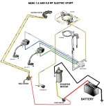
So lead from the regulator to starter solenoid - battery (hot) to starter solenoid (normally red wires). I personally would run a second hot line from the regulator to feed the start switch (which then feeds solenoid) just so when "cranking" the full amp draw is not passing through your start switch.

Then feed the starter from the solenoid with a yellow wire (makes tracing/troubleshooting easier).

Likewise, your black from the battery can terminate at one of the mounting bolts for your rectifier/regulator OR one of the mounting bolts on the starter (whichever is convenient) - any good "ground point" on the block is fine.

Here's a diagram...starter wiring.jpg
 
Last edited:
You can hook all your "hot leads" at the starter solenoid (typical) - no problem there.

So lead from the regulator to starter solenoid - battery (hot) to starter solenoid (normally red wires). I personally would run a second hot line from the regulator to feed the start switch (which then feeds solenoid) just so when "cranking" the full amp draw is not passing through your start switch.

Then feed the starter from the solenoid with a yellow wire (makes tracing/troubleshooting easier).

Likewise, your black from the battery can terminate at one of the mounting bolts for your rectifier/regulator OR one of the mounting bolts on the starter (whichever is convenient) - any good "ground point" on the block is fine.

Here's a diagram...View attachment 13147

Graham, This makes complete sense! Thank you for verifying all of this for me, and helping me out!

You're a real MVP!

Thanks again!
 
Back
Top