Logo

Proper pick up gap

michael.stinson

New member
I am replacing the pickup in the distributor of my port engine. I am looking for someone that can tell me the proper gap to set as I have received several answers from others I have asked and the pickup did not come with any information.

Thanks for reading and for any help possible

Mike
 
Sorry for the lack of information on my post.... I am working on a 1980 Chrysler lm318 with electronic ignition. I have a new cap, rotor and pickup and am unable to find any specs on the proper gap. I have been told anything from .006 - .018. Thanks for the 2 previous responses and that is what I will do if I cannot get the specs that are in the book.

I would also be interested in finding out where I can purchase a full service manual for the engine. If you know of a web site please let me kow.

Mike
1980 Silverton 31 Sean Bridge
 
Mike, is this a Chrysler VR system .... or something other than VR... such as a Hall Effect unit?

If VR, it's advised that a non-conductive, non-magnetic plastic gauge be used to check the gap.

And by the way.... and not often mentioned ...... the proper gap does control the dwell angle.


.
 
Chrysler electronic is .006" - .008" gap using non-magnetic (brass, plastic) feeler gauge.

Search the net for "Chrysler Marine Engine Startup Facts" for a decent general engine book.
 
our host, ME.com, offers many editions of the factory manuals....see the link at the top Boat Motor Manuals...
....
 
Just set the thing close as you can without it hitting and it'll work just fine.

Jeff

PS: Made an ignition system for a 3 cylinder outboard using all Mopar stuff. The 'trigger' was a hex nut with three flats machined off--and it worked great! See what I mean? Just set it close without rubbing and go boating.
 
Mike, here is a link to a Popular Mechanics article on electronic ignitions. 6 to 8 thou using non magnetic feeler is spec. Dwell angle is a points system setting and not applicable to the Chrysler solid state ignition.

Mcomm, dwell or dwell angle represents the time at which the ignition coil is being saturated or charged.
In a Kettering system (contact points), this occurs during when the contact points are closed.

Let's take an 8 cylinder engine for an example.
8 divided into 360 = 45 ... or in other words, 45 degrees in which to close and open the contact points for one cylinder.
So if using a 30* dwell angle, the system is given 15* of open time, and 30* of closed time per cylinder.
The 30* is the dwell angle.

When we replace the contact points with an electronic triggering means, we still need coil saturation and field colapse time.

The width of the magnetic field (VR or Hall Effect) or the width of the infra red beam (photo-eye), plus the gap between the two, all equate to dwell angle.
These are generally fixed at the factory, and do not require any further adjustment.

I think that back in 1975 when Mort Schultz offered the article, he skimmed over this for the sake of keeping it simple.


.
 
Mike and all, in retrospect, perhaps should have said; "And by the way.... an incorrect gap may cause a change to dwell!"
Would that sound better to you guys? :D


I read the PDF file. Perhaps the author saw no need to elaborate any further since these systems are pre-set and require a prescribed gap.
But let me explain what I've learned about this... and I may not be 100% correct.

We all know that an ignition coil's primary winding must undergo saturation time (either via dwell angle, or dwell by ms of saturation time) and that the ignition coil's primary winding must be allowed to collapse in order for the secondary winding to produce a high energy spark.

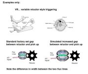
To the best of my knowledge, Chrysler Marine OEM has used the Chrysler auto VR system (I.E., variable reluctor) modified for Marine use. Similar to other magnetic triggering devices, each reluctor wheel "point" sets up a field of energy as it passes by the pick up coil. This can be refered to as a flux field.

If we deviated from OEM spec (gap between the reluctor wheel point and the pick up coil), don't we essentially also make a change to the flux feild's width?
If that answer is yes......, then doesn't that also affect the dwell or dwell angle to some degree? (no pun intended)

Here's my rather amaturish drawing.
Note that I'm showing one flux field being larger as a result of the larger gap.
 

Attachments

  • VR change to dwell angle explained .jpg
    VR change to dwell angle explained .jpg
    53.9 KB · Views: 36
Back
Top