Logo

1972 50 hp Johnson with hydro electric shift

tinocker

New member
Would anyone happen to have the electrical schematic for the motor and controls? I'm a little lost, and could use some help. Thanks.
 
Really no need for the schematic... simple wiring setup. Should become clear with the following:

(Hydro Electric Shift System Explained)
(J. Reeves)

NOTE 1 -The ohm reading of the individual shift solenoids should be between 5 to 6 ohms. The ohm meter should be set to low ohms. The shift wires leading to the solenoids must be disconnected when being tested.

NOTE 2 - The solenoid plunger measurement must be made with the solenoid placed within the lower unit. The measurement must be approximately 1/64" beneath the top surface of the solenoid... NOT above the solenoid surface nor any lower than 1/64" of the solenoid surface. This factory measurement is critical and will not ever change UNLESS someone has tinkered with it.


The shifting setup of the lower unit is what's called a "Hydro Electric Shift", which is quite complex consisting of voltage being applied to solenoids in the lower unit which in turn change oil passages via a oil pump that supplies various pressure on a spring loaded shifter dog. The wires leading to the lower unit (at the powerhead) are "Green" and "Blue". The engine must be running or cranking over in order to shift out of forward gear.

You CAN NOT use HI VIS lube in that lower unit. You MUST USE what OMC calls "Premium Blend" lube, commonly called "Type C". (A thinner lube)

Note: The engine must be running OR have the driveshaft turning by some other means in order for the engine to shift.


In neutral, you need 12v to the "Green" wire.
In reverse, you need 12v to both wires, the "Green" one and the "Blue" one.
In forward, there should be no voltage to either wire. (The spring loaded shifter dog forces the unit into forward gear)


To check the lower unit for proper shifting to make sure you have no trouble there, remove the spark plugs to avoid problems and to allow a higher cranking speed.


This next step eliminates the actual shift switch in case problems may exist there.... Disconnect the blue & green wires at the knife connectors (the rubber insulated boots) leading to the lower unit at the powerhead, then using jumpers, take voltage direct from the starter solenoid to apply voltage to the "Green" wire for neutral, then both wires 'Green" & "Blue" for reverse (Remember the engine must be cranking over in order to shift).

With no voltage applied, the unit should be in forward. No need for a ground jumper... the lower unit's already grounded. You may crank the engine with the key switch or by energizing the starter solenoid with a jumper wire.

Thousands of parts in my remaining stock. Not able to list them all. Let me know what you need and I'll look it up for you. Visit my eBay auction at:

http://shop.ebay.com/Joe_OMC32/m.html?_dmd=1&_ipg=50&_sop=12&_rdc=1
********************
 
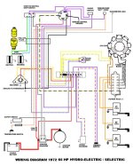
Thank you. I have already verified the electric shift is working. What I am looking for is where all the wire for the motor and the controls connect. Someone has disconnected everything "not very nicely" and I am looking for a diagram if anyone may have one. A diagram of both motor electrical connections and controls electrical connections. Thanks
 
I don't have the 50hp, but here is the 65hp. Control should be the same, motor same except for being a 3-cylinder with one more coil, etcl
 

Attachments

  • Wiring 1972 65hp  Selectric fr verified.jpg
    Wiring 1972 65hp Selectric fr verified.jpg
    86.5 KB · Views: 1,374
71_50HP%20WIRING%20DIAGRAM-grp_zps7lmmxwae.jpg
 
joereeves, I really appreciate the schematic! The problem is when I print it out it's unclear on colors and locations. I hate to be a burden, but would you happen to have a clearer image?
 
Send me a PM with your email address and I'll send you the two part full page diagram attached. Just remind me of what your email is about. (Joe)
 
Back
Top