Jeff, good choice on the connecting rod length and with going with the later cylinder block that will be roller cam capable.
Your KB piston selection is currently at a 4.000" bore. If you're going .030" over, this part number needs to be changed.
Yes, I just provided the link to them when you go on the site you select the bore oversize.
1.... They will balance all as an assembly.
2.... See above.
3.... Not only less expensive, but as said, all must be balanced as an assembly.
Why do it twice, and pay for it twice?
A little clarification needed here. The kit can come either balanced or unbalanced. Unbalanced I would have balanced locally with my flywheel and likely to better tolerances than these kits are packaged. The resellers madify these packages all of the time and mine would be no exception. (Thinner rings, and pistons to accommodate them) would likely weight just a bit different yet the reseller would not likely balance. I wouldn't save anything using my flywheel because they mass balance these things but I would get a better balance job having it done local. Hotrodders would all say have it done local for better results. Also if any machining was needed anywhere on pistons or rods better to do that before balancing.
If you are going with a Closed Cooling system, you can use High Performance automotive head gaskets with no issues whatsoever.
You'll find a greater array of compressed thickness's with the HP Auto gaskets.
Understood but have no problem with .039 and I just do not see closed cooling in the budget 
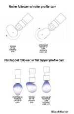
1.... Roller Cam Followers are often specific to the actual cam profile and radius.
DO NOT mix/match without first having varified.
I am 99.9% certain GM works with that cam but will verify. I believe I did ask that but can't remember for sure now.
2... with your new Q/E build, and in order to take advantage of the Quench Effect, your ignition TA will be increased. If you will be using an EST system, make certain that the ignition module offers the correct BASE and TA.
I could use more guidance here but also remember that cam typically has 4* built in to it. Something to keep in mind.
3.... What is the cost comparison when you add shipping? As I see it, you'd be paying for shipping TO YOU, and again for your cores back TO THEM..... yes/no?
Your machine shop will varify your castings for fractures prior to doing any work.
Shipping for t two is $40 and returns are included in that. I could get those in 906 casting. Could get one in 906 casting and would match the head that did not get freeze cracked. Could buy 2 and sell the three I have etc. Just something to consider.
Again, I'll suggest that after all of your components have been selected, call a reputable camshaft manufacturer, and ask for their recommendation.
Did that with what I have on the bottom end and what I have in mind for the top end and this is one of 2 the Comp cam tech gave me.
Your bore will be 4.030"... not 4.125" ..... (4.125" is the SBC 400 cu. in. standard bore dimension)
Cylinder bore is 4.030 Felpro marine gasket bore size for SBC is 4.125. I sought out and use this dimension in precise SCR calculation.
A quench of .044" should be OK.
1... I dislike the Edelbrock carburetors... and would much prefer the Holley spread bore Q-jet replacement.... but this is an idividual choice.
Your call!
2... the Performer is a dual plane manifold and will work just fine
IF you go with a Closed Cooling system.
In spite of what you're hearing, you will eventually have electrolisis and galvanic corrosion issues if the engine is raw water cooled... even if operated in Lake/River water. If may be OK for several years, but it will eventually cause problems.
I fully understand that after some undetermined amount of years this will likely happen depending on conditions they are exposed to. However I am considering it because, I am in fresh water, at least this season the boat will be trailered, I pull the thermostat annually for winterizing, at 1/3 the cost for the marine version I could replace almost 3 times (gaskets would make it more like 2) before I was at break even point.
Not normally the way I do things and I may be nuts for considering it but economically it is making some sense.
3... The OEM Merc ignition is EST, and is set up for the dreaded GM full dished pistons and related non-aggressive "progressive" and "total" advance that these engines require in order to combat Detonation.
My question would become..... "Why go to the trouble of building a good Q/E into this engine, if you're to hold back the TA?"
This is all about obtaining a good LPCP.
Jack also asks the question re; the Merc module curve, and I believe that this would be very important to look into.
(keep in mind that Merc has designed their EST system to work with the GM full dished pistons.... not a good Q/E build)
If you can find a module that meets your new requirements, go for it.
 I am not sure but it seems like this ignition can give all the timing advance I need.?
Edit:
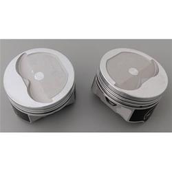
One more thought..... if you increase the intake valve diameter, it may create the need for larger intake valve reliefs in the piston decks... of which may lead to 4 piston part numbers, instead of only 2 part numbers..... of which is no huge ordeal.
Your machinist should be able to advise you.
I would suggest going larger for a 6.3L build.
Negative. Larger intake diameter can actually reduce performance on the vortec head. Small gains can be had in certain areas but at great risk and cost. The exhaust side is the weak side but here the restriction is my stock manifolds anyways. Not likely to do anything with them as they really are GM's best low lift flow head as stock. There are others that perform better after exhaustive modifications but these really do seem to fit the bill quite nicely.
.