Logo

Evinrude Sportfour 1967 60HP

Mikka8701

Contributing Member
Model 60652 Evinrude

I have recently installed NGK BH8S plugs and gaped them to .030 however when I do this the magneto doesn't spin fast enough when cranking to give a spark. However when I changed the gap on the plugs to .024 it requires a slower speed on the magneto to spin to give a spark however I am not getting a fire on any of the cylinders and each plug has a strong blue spark.

I am pulling out my hair with the amount of money I have spent on this engine just would like a solution
 
You are not paying attention......OR.....you are not answering our questions. Do you or do you not have a good spark off the coil at cranking speed? It should jump a minimum of 3/16" at that point at cranking speed. Without having the answer to that question, we are wasting our time.

After it is determined if you have an acceptable spark off the coil, THEN and ONLY THEN can you move on to a spark test at the plug wires. If you only have a short, weak spark there, the first (but not only) suspect is the distributor rotor. Other suspects are a cracked or carbon tracked distributor cap, a missing carbon brush, and bad spark plug wires (test the continuity).
 
Agreed.------------There is a need for meticulous work.-----------Cleaning and setting the points is critical.---They must be absolutely clean and timed to open relative to the rotation of the magneto rotor.------------Use the timing marks on the magneto and a meter to set the points.----------With a new coil , clean points and good condenser you will get a miniature electrical storm when spinning it by hand !!!!!!
 
You are not paying attention......OR.....you are not answering our questions. Do you or do you not have a good spark off the coil at cranking speed? It should jump a minimum of 3/16" at that point at cranking speed. Without having the answer to that question, we are wasting our time.

After it is determined if you have an acceptable spark off the coil, THEN and ONLY THEN can you move on to a spark test at the plug wires. If you only have a short, weak spark there, the first (but not only) suspect is the distributor rotor. Other suspects are a cracked or carbon tracked distributor cap, a missing carbon brush, and bad spark plug wires (test the continuity).
I have good spark of the coil tower and I have checked the spark from the Leads which is a strong Sparks I believe that the sparks are great and that the carbon is not cracking and the rotar is not shorting out
 
So you have spark that will jump a gap of 1/4" or more on each plug lead ?------------Motor will not start and run?----------Next is to look at fuel delivery issues !!
 
Yes all compression was check by my mechanic and all cylinders are within 10 of each other cyld 1 94 cyld 2 86 cyld 3 96 and cyld 4 87psi
 
Since no one here is standing beside your motor , many have asked questions.-----You seem reluctant to answer the questions.-----You go off on your own trouble shooting path and ideas.-------This approach is not going to get this motor running.-------Sorry for being blunt here.
 
I apologize for being so blunt also. I have no doubt you checked those things, but what we need is an answer as to what you found. We need your input to clue us in to where to go from here.
 
Well good news I got the engine starting as it turned out to be the screw on the external casing that has the kill wire turn out the insulator was shorting out to the casing producing a weaker spark...
problem is the engine is still only running in two cylinders let me know what I should do
 
There are two different rotors... one being for the automotive system, the other for the magneto system, and they are not interchangable! Make sure you have the proper rotor.

Automotive system rotor (580338) business end = straight squared off end.

Magneto system rotor (580260) business end = weird looking hook shaped end.

Spark from the coil button should jump a 3/8" gap with a strong blue lightning like flame... a real SNAP!

The magneto has two sets of points... one fires the port bank, the other fires the starboard bank. Set the points on the high lobe so that a .020 gauge slides thru BUT a .022 will not. The points can be cleaned with either acetone or lacquer thinner. Note that the oil simply from a finger print will interfere with the ignition process.

A word of advice, meant in the best possible manner.... things that agravate someone trying to help another, for example.... one would ask if the spark jumps a 3/8" gap... or asks what the actual compression psi is on all individual cylinders. Later, that person receives a reply that states a generality such as... the spark is great and the compression is okay. This tells us nothing and as you can see above, it does get old pretty quick with various members.
 
Thanks for the detailed response.
When you were talking about the points controlling different sides of the engine plugs do you think that one of the points could be not making good enough contact?
 
Thanks for the detailed response. When you were talking about the points controlling different sides of the engine plugs do you think that one of the points could be not making good enough contact?

That's my line of thought at the moment... Also be sure of which rotor you're using.

You need to first be sure if you're obtaining spark (proper spark jumping 1/4") at all plug wire to plug connections. If you do, then the problem would most likely be carburetion rather then ignition.

I prefer Champion J6C plugs gaped at .030 (OMC's recommendation).
 
Last edited:
I am using an automotive system rotar. When I start the engine what happeneds is the engine will change idle speeds constantly revving to high and low intermittently without me touching the accelerator. I know from past experience if you pull the plug lead off the spark plug you should notice a decrease in performance this is the case for two cylinders on the port side but on the starboard side the engine is not affected in anyway which leads to me thinking that there is no firing. I will check the spark gap tonight coming from the leads and get back to you. I might post a video and send you the link if that helps let me know?
 
We have a problem here. The title of your thread says you have a 1967 motor, but the model you gave (60652) is a 1966. The statements you have given also indicated it is a 1966. I point this out because they take different rotors. If you are certain that you have the automotive (battery ignition) system rotor, that would be correct for a 1967, but wrong for a 1966. Please verify.

The plugs you have in there may not be ideal, but it should at least start and run on all 4.
 
Last edited:
I assumed they were both interchangeable given that it has an automotive rotar and the model is 60652 let's assume it's a 1966
 
Look closely at this picture. Does yours look exactly like this? If it does, you have a 1967 battery (automotive) ignition system rotor and it needs to be replaced. The 1966 magneto ignition rotor does not have a square tab like this one. The tip is wider on the mag rotor.
 

Attachments

  • dist rotor.jpg
    dist rotor.jpg
    32.4 KB · Views: 94
There appears to be a bit of confusion here. To assure that all of us are on the same page about the ignition system.... check the following and let us know which you have.

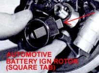
Automotive ignition = Distributor cap attaches to the top of the distributor... plug wires exit the top sides of the cap.

Magneto ignition = Distributor cap attaches to the bottom of the distributor... plug wires exit straight down out of the bottom of the cap.

The 1966 V4 would have a two barrel downdraft carburetor. There would be two brass high speed jets located horizontally way behind those two 7/16" slotted hex head drain bolts you see at the bottom front of the carburetor. Clean them carefully with a piece of single strand steel wire... they must be perfectly clean. Adjust the slow speed needle valves as follows:

(Carburetor Adjustments - Older V/4 Downdraft Carb)
(J. Reeves)

NOTE: The early model downdraft carburetors incorporated "Adjustable High Speed Jets". The later model downdraft carburetors used "Fixed High Speed Jets". The high speed jets would be located in back of the two bottom drain screws. Follow the below instructions accordingly.

NOTE: If you do not have adjustable high speed jets, ignore those paragraphs pertaining to same...... BUT do make sure that you manually inspect and clean the two brass fixed high speed jets which would be located in back of the two 7/16" slotted hex head bolts in the bottom front portion of the float chamber.


Lift the center High Speed Control lever and turn it so that the point faces forward, resting on the high ridge. This will disengage the lever control gear from the individual high speed jets (slots). Have the slow speed needle valve knobs installed upside down so that they can be turned without encountering any obstruction.


Gently seat each of the High Speed needle valves, then back each one out one (1) turn. Gently seat each of the Slow Speed needle valves, then back each one out one and one half (1-1/2) turns. NOTE... have the jam nut on the s/speed needles snug so that vibration won't have any effect on them, but loose enough so that you can turn them without a great amount of effort.


(High Speed)
With a reliable person at the wheel, and one kneeling in front of the engine, start the engine (yes, it will run lousy with the above initial needle valve settings), put it into forward gear, and apply full throttle. Start with the High Speed adjustment on the left using a screwdriver that properly fits the slot.


(High Speed Adjustments)
At full throttle, with the proper size screwdriver, slowly start turning one of the H/S needles in segments of 1/8 turn, waiting momentarily for the engine to respond, then repeat turning. You will reach a point where the engine will start to die out. At that point, back that needle valve out approximately 1/4 turn. Now, go to the other High Speed needle valve and repeat that procedure. At some point in that 1/4 turn out, you will find the smoothest high speed setting (you can now lower the throttle rpm). That will have both high speed needle valves set correctly, and at that point you can lift that center lever adjustment of that high ridge, keeping it lifted until the point is facing the engine, then lower it into its proper position. (When you turn that lever now, you're adjusting both High Speed needle valves at the same time.)


(Slow Speed Adjustments)
Now, lowering the rpms of course, take the engine out of gear and set the throttle just to where the engine will stay running. Again, in segments of 1/8 turn, slowly start turning in one of the slow speed needle valves, waiting a few seconds between each turning for the engine to respond. As you turn the s/speed needles in, the rpms will increase..... and as it does, lower the rpms to where the engine will just stay running (otherwise the rpms will climb quite high). You will reach a point whereas the engine will either start to die out or it will spit back (sounds like a mild backfire). At that point, back the needle valve out 1/4 turn. Repeat the process with the remaining slow speed needle. Again, at some point in that 1/4 turn out, you will find the smoothest setting. When finished, tighten the jam nut somewhat, then remove and reinstall the s/speed knobs correctly (right side up).
 
So as I can rule out timing being an issue does anyone know how I can line the magneto up up with the crank shaft I know on the block there is a line to line the crank shaft but I no longer have a safety switch on the engine to line the magneto up with ?
 
Are you gonna be doing the service work on your motors? I will allways get a service manual for any engine I work on. You can allways put the #1 cylinder on TDC and point the rotor at the #1 plug wire tower on the cap?
Yes Iwill be doing work on my engine I know I should probably buy a service manual. I have uploaded a video on YouTube of how the motor is currecntly running tell me what you think http://youtu.be/BYD7KVeK0GI
 
So as I can rule out timing being an issue does anyone know how I can line the magneto up up with the crank shaft I know on the block there is a line to line the crank shaft but I no longer have a safety switch on the engine to line the magneto up with ?

So the safety switch is missing, but the screw holes are still there. The switch button was centered between those two holes.
 
Sorry about that video is now not private anymore.check it out . My controls do not have a safety switch but I do have the holes where the safety switch used to be so how do I line up the magneto?
 
Back
Top