Logo

AQ280 Prop rotation

When i added new gauges and switches for the tilt i used a (on) off (on) momentary switch and 1 LED for the light. The LED comes on when the drive is completely down.
Is there a way to add another LED to come on when the drive reaches the full up position?

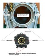
Pat, as the drive is lowered, the vice rod becomes fully retracted into the housing.
When it reaches full retract, it operates the micro switch (inside of the black plastic relay box).
As the micro switch is depressed, it opens the negative circuit for the electric motor (preventing clutch damage), and also closes the negative the circuit for the amber light at the helm switch.

As the drive is being raised, the vice rod is being extended, leaving the proximity of the relay unit.
So basically there is no OEM provision to operate a "full up" indicator light.... at least none that I am aware of.


BTW.... and you may already know this.....
On your 280 drive this is a "lift out" unit only........ not a Trim unit!
However, if very careful it can be used to raise the drive in shallow water when in FWD gear ONLY and at idle speeds ONLY.


**********************

NOTE for Pat or any on lookers:
Do Not circumvent the realys and/or micro switch in an attempt to operate and test the electric motor.
If the vice rod is fully retracted without the micro switch in the loop...... you'll risk breaking the cast iron portion of the clutch.

.
 
The only "indication" I've noted on several versions of the 200 lift system is that in the "full up" position, the electric motor "stalls" and makes a "groaning" sound as it slows to a stop. The best way to make an "full up" sensor ( I've toyed this the idea a number of times") , would be to tape a hall effect sensor to monitor the currect on the feed line to the motor with some electronics to drive an LED. I thought about the simpler solution of measuring the voltage @ the motor, but a low battery condition would give a false indication.
The Hall effect sensor is doeable, however, I feel (even with a degree in electrical engineerin) that it's not worth the trouble to do it for my boat, and that there isn't a big enough market to justify the development of one as a product. I also toyed with the idea of a magnet on the top of the drive housing and a reed switch behind the "bumper pad" on the transom shield, but felt the installation issues made this dubious.
Sooo... I "listen for the groan" :)
 
Mine is pretty quiet and even more so now that i have cleaned it and got it working smoothly. Last year i had to really listen to it as it sounded almost the same at all times.
Now that i have cleaned it i think the ambient noise at the launch/dock will just drown out the noise of the tilt mechanism. Guess ill just walk to the back and look. Maybe add a tilt switch in the rear of the boat so i can watch it.
Or maybe timing it and just start counting when i push the up button.
Or maybe some kind of timer to shut it off after a set time.
Hmmmm Just seems easier to walk to the back and look.
 
Thanks Ricardo.
I did know it was for tilt only already but i did not know with out that switch on top it could break!
I got lucky i guess because i was using it last year with the relay box just lose on the shaft not held down. Discovered by accident how to get it held down.

Got the 290 exhaust flapper mounted today. Pretty easy job. Took about an hour and 100 dremel wheels!

Man anyone ever notice that it seems like no matter how much you do there is always more to do:rolleyes:
 
Pat, yes, I agree, the lift unit is quiet... so quiet that it's hard to hear, especially if the engine is running.

The Lift Out unit has a protective clutch within it, and it is designed to slip in one direction only, as in if the unit was raising the drive beyond the limits.

It also allows the drive to go Full In in the event that we would power-up while the drive was slightly lifted.
However, Use Caution...... in some cases the vice rod will bend if we were to power-up when lifted.

Man anyone ever notice that it seems like no matter how much you do there is always more to do:rolleyes:
Pat... it never really stops! ;) But, it will taper off!


.
 
Last edited:
Well... after rethinking my previous comments about a drive up detector product, realized that a simple solution would be to attach a magnet to the top of the drive on a S/S bracket that would extend the magnet to the side and forward. Then attach a sealed reed swith on the transom next to the bumper pad so that the magnet on the drive is close to, but not touching the transom mounted switch. Wire that switch to block ground on one end and the other end via a long wire to a panel mounted LED that goes to the instrument panel's +12 bus. This is the same thing as is used as a "door open" switch in building alarm systems. You may be able to find a water proof one.
 
Last edited:
Pat, while in neutral, and with good batt voltage, the lift out unit will typically lift within a certain time frame.
Train yourself as to the time required for a full lift out.
 
Yeah sandkicker its just easier to not do a thing about adding a light.

Which is why, since getting my first boat w/ a 200 series drive in 1979, I never bothered for the one or two times a season I ever lifted the drive. You might want to glance @ the voltmeter on your dash ( if you have one). The battery voltage should dip slightly when the motor loads up and stalls when the drive is all up.
 
Well not really boat related but kinda is.
Bought a new to me(used) tow rig today. 1994 Chevy LD3/4ton 4x4. 5.7, 4L60E, It will tow my boat with no problem im sure! A LOT better then the ole Isuzu Rodeo 4X4 did.
 

Attachments

  • IMG_20150320_094009_425.jpg
    IMG_20150320_094009_425.jpg
    59 KB · Views: 47
  • IMG_20150320_094033_516.jpg
    IMG_20150320_094033_516.jpg
    77.4 KB · Views: 43
OK PICTURE TIME!!!!
This is what we have been working on over the winter. Its still dirty and the back seats are out but its basically done.
Had it at the lake today for about an hour and all worked fine mostly:cool:
3 Small issues
The Quadrajet does the Quadrajet bog so i need to adjust the secondaries but the rebuilt carb works fine other then that and a little tuning will fix it.
The shift cable needs adjusted
Prop seems like it needs more pitch. It is 15.5X17P cup. I ran it at 3500 rpm(checked with boat tach and hand held) and got 32mph. Forgot to check gps so that's what the boat speed'o said. WOT was 4400 right on the spec but i do think it will still reach 4400 with more pitch
I'm thinking a 21P would be more for me. I don't pull skiers. Just race from one fishing hole to the next!
 

Attachments

  • IMG_20150329_132759_781.jpg
    IMG_20150329_132759_781.jpg
    50.6 KB · Views: 49
  • IMG_20150329_132818_736.jpg
    IMG_20150329_132818_736.jpg
    56.5 KB · Views: 42
  • IMG_20150329_132842_343.jpg
    IMG_20150329_132842_343.jpg
    65.3 KB · Views: 54
  • IMG_20150329_132912_220.jpg
    IMG_20150329_132912_220.jpg
    86.3 KB · Views: 49
  • IMG_20150329_132923_453.jpg
    IMG_20150329_132923_453.jpg
    63 KB · Views: 36
  • IMG_20150329_140040_097(1).jpg
    IMG_20150329_140040_097(1).jpg
    66.3 KB · Views: 44
Last edited:
Do Volvo Penta 280 drives need alignment? I have searched and can't seem to find any info about it but can find a tool that says fits Merc and volvo.

Reason i ask is. I discovered the two big nuts on 1 motor mount are lose and are about 3/4in lower then the other side. I raised it up so its even with the other side but after thinking about it, it may have been the wrong thing to do?
 
Pat, yes... there is a one-time-alignment that must be done each time that an engine w/flywheel cover is being R&R'd.
This involves a triangulation procedure.

If your engine mount stud nuts became loose, at best you'll be guessing at the height adjustment.

To do this correctly, you'll need to remove the transmission, loosen the clamping ring bolts, and start the triangulation procedure from scratch.
The goal is to achieve equal distance or space between each set of flats in three locations........ 9:00, 12:00 and 3:00 O'clock.
You'll be using the engine mount stud adjustment to change the dimensions.
Once equal distance/space is achieved at all three areas, you'll tighten the clamping ring bolts.
 

Attachments

  • Initial engine alignment triangulation 2.jpg
    Initial engine alignment triangulation 2.jpg
    60.5 KB · Views: 54
Thanks Ricardo.
With the transmission removed could you explain where to measure from with the drive installed? I can't visualize where i can measure from 3 equal destance spots.
 
Actually think i figured it out.
Loosen the 6 bolts, Measure from the inside of the red thing to the center of the drive shaft and adjust motor mounts until its centered in the hole then tighten it all back up and recheck. Do i have it right?
 
Actually think i figured it out.
Loosen the 6 bolts, Measure from the inside of the red thing to the center of the drive shaft and adjust motor mounts until its centered in the hole then tighten it all back up and recheck. Do i have it right?

Pat, take another look at my image.
I have drawn arrows pointing to each of the six flat areas. Three on the transom shield and three on the flywheel cover!
When grouped in twos, there will be three locations.
9:00, 12:00 and 3:00 where 3 of them will correspond to the other three.
When the distance between each of the two corresponding flats (three areas total) are equal, you are in alignment.
This is Triangulation!!!!

.
 
I guess im not understanding totally.
Waite. Maybe im thinking the wrong way. Am i trying to center the drive shaft in the red part where the aft pds bearing is. I measured there and its so close i cant adjust it any better then it already is.
OR
Am i needing to center the bell housing to the transom shield?

Pat, the primary driveshaft is fixed geometry… There is no changing that.
You will be centering the flywheel cover into the transom shield using the triangulation process, via the three measuring points.

The goal is to obtain an equal squeeze on the two rubber cushion rings creating a good seal.


.
 
Last edited:
Thanks ole wise one:)
I understand now. This is tomorrows number one project!!! after replacing 2 windows for the boss lady around here:rolleyes:
 
Back
Top