Logo

Retro fitting Closed Loop cooling to 5.0 GXi-F V8

nimbus

Member
Hi Folks
I am a newby here having just bought a 2006 Monterey 194 sports fitted with a 5.0 GXi-F V8 motor with 400hrs on the clock.
This boat has been meticulously looked after has run in mainly fresh river water and has lived on a trailer.
However I need to leave it in salt water at my daughter's jetty north of Sydney Australia, I am looking at buying a "boat bag" which I am told do work very well.

My question is this: I am seriously considering converting the engine to closed fresh water cooling for obvious reasons!!! (closed loop) including the manifold and risers.
Has anyone out there done this on a Volvo engine???
I would appreciate your comments
 
Conversions of engines run in raw water to closed cooling is considered by some to be problematic due to the difficulty in getting the existing water jackets ( block, manifold) clean of crud and corrosion. Should you be able to do this satisfactorily, then you need to buy an aftermarket kit which includes all the parts. There are generally two flavors of closed cooling systems around and the difference is in one system (Full) the exhaust manifolds are "inside" the closed system and in the other (partial), the exhaust manifolds are raw water cooled. The partial systems get away with a smaller and cheaper heat exchanger and can usually use the existing raw water pump. The partial systems tend to be subject to shorter life of the manifolds. In BOTH systems, the elbows (or risers) as you called them are ALWAYS raw water cooled since the elbows are used to dump "used" raw water into the exhaust stream.
If you buy the kit for your specific system it should come with all the parts you need. Note that one of the big changes is the plumbing associated with the elbows. A special blockoff gasket is needed in Full systems between the manifold and elbow to isolate the fresh water (actually an antifreeeze water mix) inside the closed cooling system from the raw water that is dumped overboard. Given shipping costs, you should try to source this kit locally. There are two major USA based manufacturers of these kits who might have representation in your area. Sen-Dure and SeaKamp. There is another company that advertized kits for Volvos but they only list partial (block only) kits.

In addition to possibly having to change the raw water pump for a full kit, you may have to convert to a thru hull water pickup ( use a strainer) since the water flow requirements for FWC kits is higher than for a raw water cooled engine and some kits specify a 1-1/4" water feed which I believe is larger that the feed from all Volvo lower units ( it is larger than the feed from 200 series drives, for sure). Usually the thermostat is changed to a 160 ish degree F T'stat since raw water engines usually have 130 T'stats as the higher temp T'stats give better engine efficiency as well as other advantages.

Most suppliers of these systems strongly recommend discussing youf project with them before buying anything. I've had both Sen-Dure and SeaKamp systems on my boats over the years and have talked to their customer support ( a real engineer!!) and have found them to be very helpful. While I've converted MERC and Chrysler engines, I've never personally done a Volvo.
 
Last edited:
Bob is correct and has offered you some good information!

If the exhaust manifolds will allow, it can be done in both a full or half system, but there will be some potential issues that will need to be dealt with!

Perhaps do a forum search, or click on my username and look at previous postings… I know that I have commented on this several times over the years.


.
 
Thank you sandkicker and Richard for some excellent and sensible advice on closed circuit cooling.
Unfortunately I have not been able to locate any local distributers in Australia. I Have however been talking to Ricky of PPT sales who has been very helpful.
They make a 4"dia by 26" long all copper silver brazed exchanger which is attractive to me.
The problem as I undestand it with the Volvo engine is that the risers or elbows do not have the extra screwed attachement that can take the input water, like the Merc units have.
However I do have my own well equiped workshop with lathes and milling machines (I make 5" gauge passenger carrying steam locomotives as a hobby) so I am in a position of modifying the elbows if I had to.
Other people that I have talke to reckon that the full system is better as it protects the manifold.
As for the accunulated gunge in the block this is a problem and I thought of using a dilute acid wash (sulphuric acid), would this work??
I have not come across sen-dure or seaKamp in my searches do they make their own systems or are they suppliers of another manufacturer??
 
Sen-dure and SeaKAmp are OEM manufactureres of closed cooling systems. Often, closed cooling system are distributor or mechanic installed as customer ordered options on engines that come from the factory, e.g., MERCRUISER, as raw water cooled engines. I just looked at Sen-Dure's webpage. The apparently no longer list FWC kits. Contact SeaKamp Engineering and see what they offer.
 
Thanks sandkicker,
I have checked seaKamp they make a whole range of units for the Merc but non for the Volvo it seems.
PPT sales do offer a Volvo unit but only half cooling not full. I will probably go for their 4" dia. X 26" I think I do have enough room in the engine bay
to fit it off the engine using universal cut-to-length hoses.
I notice that most of the exchanger units are designed for horizontal fitting, however IMO this is not ideal. Would it be better to fit them vertical so that the down pressure of the water keeps the barrel completely full of raw water at all times with no air.

The only half cooling issue is as you noted related to the lack of an injection point on the elbow. Depending on how badly you want a full system, you have two options: 1) as you noted you have machine shop capabilities. It would be simple with minimal tools to drill and tap the elbow for a bronze nipple for the necessary hose, however the issue for me would be if the wall thickness would be thick enough for the threads. Traditionally the injection point is at the bottom of the elbow facing the front of the engine. I would be concerned that you would have enough wall for the nipple to screw in and seat (tapered) and not intrude into the water passage impeding flow. You could cut the threaded end of the nipple short, however. The other thing you would need to do is install a "blocking plate" at the elbow/manifold junction. To do this... buy 2 sets (4 total) of the standard gaskets used at this juncture. Using the gasket as a pattern, fabricate a stainless sheet blocking plate with only a single large hole for the exhaust, i.e. no water passage. Assemble a sandwich consisting of a standard gasket, stainless block plate and a second gasket for each elbow.
2) Pricey, but simple.... scrap the existing Volvo manifold and elbow and replace it with a MERCRUISER set. Some gurus think that the current production MERC elbows give better protection from water reversion into the engine that most other (except Crusader) elbows.

My current setup has a 5.7L MIE MERC FWC engine in front of a 280 drive. The connection between the elbow outlet (4") and the Volvo "Y" consists of a 4 to 3" adapter, and a 72 (?) degree elbow and some short lengths of 3" exhaust duty hose to a cut down standard "Y" pipe. The FWC is a SeaKamp aftermarket kit with a thru hull inlet for raw water.

Re: Horizontal vs vertical... The SeaKamp is mounted horizontally. This puts the fill port for antifreeze up front and "proud". A provided plastic bottle and tubing to the nipple on the fill cap mount assures the fresh /antifreese coolant side of the system if full, no voids, all the time. Since the raw water side is immediately on the high pressure side of the engine mounted raw water pump and has a down stream restriction ( dumps to elbows), the exchanger fills immediately and fully as soon as the engine runs for a second or two.

On one of my boats, there was no room for the H/E on the front (or back) of the engine, so I remote mounted it on the transom adjacent to engine. The antifreeze fill port was a pain to get to, but otherwise all was OK.
 
Nimbus, your 2006 Volvo Penta does not use an exhaust manifold and elbow like the AQ series does. The AQ series does not allow for any separation between the elbow and manifold transfer ports.
Your 2006 system may allow for this...... more like the Merc systems.

please post a few photos of your engine and exhaust for us.


Your 2006 exhaust elbows will need to be ported in order to block them off from the manifolds for a "Full" system.
Your 2006 exhaust manifolds will also need to be ported in two locations........ one for incoming coolant...... and one for return coolant...... and must be sized adequately.


If you do a "Full" system, not only will your heat exchanger need to be sized and equipped accordingly, your seawater pump volume may need to be increased also!


FYI...... it will be much easier to do what's called a "Half" system.


.
 
Last edited:
Also.... if you have a milling machine, and the room in your engine box, you could fabricate a pair of "spacers" that would fit between the manifold and elbow that would 1) block water flow between the manifold and elbow, 2) provide an injection point for raw water towards the elbow and 3) provide a return path from the manifold for the coolant that would maintain the original flow pattern of the Volvo manifold/elbow combo and 4) of course maintain the existing profile for the exhaust gas flow.
It would in outline look like your existing gasket but have a blocking web midway in the water path with threaded in and out ports either side of the web.

Since this would "disturb" your existing geometry between the exhaust outlet and the "Y" pipe, you might have to transition between the elbow and the "Y" pipe with one of those "flexible" silicone exhaust hose sections.
 
Bob, once past the AQ series engines, the Volvo Penta exhaust system becomes more like Merc's.

I am doing this via my iPhone… otherwise I would post a few images to show the differences.


.
 
Rick,

That would make his conversion fairly straightforward, leaving as you pointed out, raw water pump capacity (and possible inlet line diameter issues). At my YC, we have two boats that see almost daily use between mid June and Labor day for management of the Junior sailing program and a race series we run Sunday mornings and afternoons. I am one of the people tasked with maintaining the boats. There are 5.7L carbed MERC engines w/FWC kits on both of them. One of the boats, a 23 ft Mako C/C inboard, has a partial kit (boat bought used), the other a full kit. This season, the manifold in the MAKO rusted thru and hydro locked the engine. Fortunately, no other damage. The boat with the full kit is older and has easily twice twice as many hours on it... still running fine.

I personally think the full kits are well worth the extra expense.
 
I agree… the full system would certainly be the way to go.
With a half system, we need to keep an eye on the exhaust manifolds, and perhaps change them every 4 or so years.

With regard to the exhaust elbows, these will need to be changed routinely regardless of which system is used.

Full system....... no draining manifolds during layup.
Half system....... manifolds must be drained during layup.
With either system...... elbows must be drained.


.
 
Last edited:
Hi Folks,
I have been away from here for the weekend crawling over the boat and engine.
The problem of wall thickness did occur to me, specially since the engine has seen 400 hrs (although in fresh water) I notice that the Merc elbows have boss's cast into the outer walls to allow for a thicker area for threading. I had determined that if I go this way, then I would machine up a couple of cast iron or naval bronze boss's and braze them to the elbows and then drill and thread them.
For anyone who has not done this before, it is not rocket science, All it take is a degree of skill with an oxy propane torch. The secret is to slowly heat the whole of the elbow to about 400degC before applying the concetrated heat at the required location. Then let it slowly cool by wafting the torch over the unit for about 2mins. In the US there would be many jobbing shops willing to do this simple job for about $100 I would think.

The idea of a thick plate machined so as to permit the attachment of two water feeds does make sense as this could then be supplied as part of a kit for Volvo engines.
I have one question: what diameter hose is required on these fittings??, as this will determine the plate thickness. Longer bolts will be required but this is not a determining problem. Should the plate be made from bronze or SS?? the bronze is much easier to machine of course especially for milling.
My "SELOC" manual arrived while typing this and it does not talk about AQ series engines.
I have had a good look at the elbows and they are very similar to images I have seen on utube of the Merc ones, they are held down by 4 bolts onto the manifolds.

I guess I do have one real concern, can this retrofit be done easilly with the engine in situe? The RHS seems easy to get at but the RHS where the alternator and oil filter are attached seems to be a real problem.
I have been considering buying a Merc FWC kit and the exhaust manifolds and elbows as has been sugested, but the problem as I see it, is that all the hoses will be for the Merc setup which will a problem.
Which ever kit I get it would seem that the determining factor will be the capacity of the raw water pump, although with the 26" long heat exchanger,this may solve the problem. I have sent some pics to Rick at PPT_sales so I will see what he has to say.
 
..................
The problem of wall thickness did occur to me, specially since the engine has seen 400 hrs (although in fresh water)
Engine block wall thickness... or exhaust component wall thickness?


I notice that the Merc elbows have boss's cast into the outer walls to allow for a thicker area for threading.
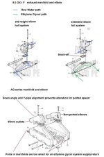
Below is an image that I put together for you. Your 5.0GXi-F manifolds and elbows should be similar.
The tall elbow style should be equipped with threaded ports. I'm not sure if these adequate for the correct size fittings.

I had determined that if I go this way, then I would machine up a couple of cast iron or naval bronze boss's and braze them to the elbows and then drill and thread them.
If the elbows are not ported from the factory, Volvo Penta may have good reason for not doing so.


The idea of a thick plate machined so as to permit the attachment of two water feeds does make sense as this could then be supplied as part of a kit for Volvo engines.
I believe that you're talking about a ported spacer or riser.
Depending on the location of the "block-off", these can be used to add porting to an elbow (block-off below)....... or they can be used for an additional manifold port (block-off above).
images


If Volvo Penta indended for this model to be "Full System" cooled, then yes.... a kit may include this "Ported Spacer/Riser" for the raw water supply to the elbow.

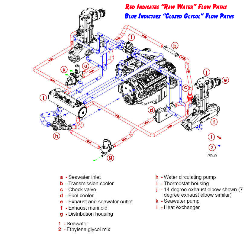
You must also consider the E/G coolant flow TO and OUT of the exhaust manifold.
If the OEM ports are not large enough, a "Full" system may not work.

I have one question: what diameter hose is required on these fittings??, as this will determine the plate thickness. Longer bolts will be required but this is not a determining problem. Should the plate be made from bronze or SS?? the bronze is much easier to machine of course especially for milling.
This would be your design......

My "SELOC" manual arrived while typing this and it does not talk about AQ series engines.
Toss the Seloc manual in the recycle bin, and purchase a Volvo Penta OEM work shop manual. (too many errors in the seloc)

I have had a good look at the elbows and they are very similar to images I have seen on utube of the Merc ones, they are held down by 4 bolts onto the manifolds.
Correct!

I guess I do have one real concern, can this retrofit be done easilly with the engine in situe?
Yes!


Which ever kit I get it would seem that the determining factor will be the capacity of the raw water pump,
That and the exhaust manifold porting, and whether or not the elbows can be blocked-off, and can be fed seawater without restrictions.

the although with the 26" long heat exchanger,this may solve the problem.
The length/size/capacity of the H/E is not your only concern.

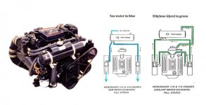
Half system = a very simple coolant outlet to the Engine Circulating pump, and a very simple single coolant return to the H/E shell.
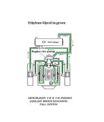
Full system = a very simple coolant outlet to the Engine Circulating pump, but a more complex coolant path for feeding the manifolds and returning from the manifolds to the H/E, and the engine coolant return path to the H/E.

Keep in mind that the worst case with a Half system, will be replacing the exhaust manifolds every X years or so.
Elbows will still require routine replacement.


In this image, I'm not implying that your OEM exhaust system is capable of a Full System......... I'm showing you what would be required.

I've also shown the AQ series exhaust system that is NOT full system capable.
 

Attachments

  • exhaust later style full or half system.jpg
    exhaust later style full or half system.jpg
    50.1 KB · Views: 794
Last edited:
I have a 280. When I went from a 283 block (4.6L) to a 350 (5.7L) and FWC I quickly found out that the exhaust system on the drive was too restrictive. Per the MERC manual for the 5.7, a single exhaust port should be a minimum of 4" in diameter, a dual 3" per side. I measured the port on a spare Volvo "Y" pipe I had and it measured about 2.95 inches effective, including allowances for the two side dumps. What prompted this research was my inability to get the WOT RPMs I expected. Also MERC said max back pressure 4 psi. I measured over 6 psi before I stopped testing. From a gas flow basis a 5.7 @ 260 HP has the same port requirements regardless of who make the engine or whose block/head it is, i.e., GM or Ford or Chrysler.

I converted my setup to thru transom, dual exhaust w/mufflers ( to comply with local regulations)... and my wife's ears.
I got an RPM increase of 500 RPMs.

If you are interested in the long version of this project...


I don't know what the exhaust port requirements are for the 5.0L, but I seem to remember that the manual for the 5.7 also covered the 5.0, so they may be the same.
 
Last edited:
Thanks Ricardo for your detailed response to my last post.
Now I have more thngs to think about!!!!
By Sheer coincidence while reading your post I got a call from Ricky of PPT-Sales who said that they now have a Volvo Penta elbow which has been designed with the required ports to take a full cooling system. Unfortunately they do not have the full kit (with hoses) available at the moment. He reckons that their 4"dia. X 26" long heat exchanger would be suitable for a full system on a 5Lt 270HP engine.
My engine bay is reasonably wide on the Monterey so I believe I would have room to fit this across the front of the engine in the normal way, however I will need to fabricate the required mounting brackets.
 
.......................
Thanks Ricardo for your detailed response to my last post.
Now I have more thngs to think about!!!!
You are welcome!


By Sheer coincidence while reading your post I got a call from Ricky of PPT-Sales who said that they now have a Volvo Penta elbow which has been designed with the required ports to take a full cooling system.
If past the AQ series..... that is a plus!

Unfortunately they do not have the full kit (with hoses) available at the moment. He reckons that their 4"dia. X 26" long heat exchanger would be suitable for a full system on a 5Lt 270HP engine.
Don't forget that the exhaust manifold inlet/outlet ports must be of the correct size also.
Too small... and you'll have coolant flow trouble.

My engine bay is reasonably wide on the Monterey so I believe I would have room to fit this across the front of the engine in the normal way,

however I will need to fabricate the required mounting brackets.
Why not give JSE (San Juan Engineering) a call?
They should be able to offer you a system especailly designed for your engine model that would not require any custom mounting brackets.


NOTE: When doing a Full System, the coolant being pumped through the manifolds must continue flowing.
Whereas the coolant flowing through the engine block/cylinder heads will be held back by the thermostat until the thermostat dictates.
Depending on engine temperature.... the engine block/cylinder head flow will vary.

These Full System T-stat housings are unique to these systems.


These two images below were drawn up for a Merc Full System scenario.... but the Volvo Penta would be very similar.

Images to the left show separate schematics for the seawater path and for the E/G path.
Note that the elbows are shown in the seawater path image (left) ..... and not in the E/G path (right).

Image to the right shows the E/G path only (no elbows shown).
 

Attachments

  • Close Cooling  schematic  for Thomas 2.jpg.jpg
    Close Cooling schematic for Thomas 2.jpg.jpg
    33 KB · Views: 1,253
  • Closed Cooling schematic  for Thomas 2.jpg
    Closed Cooling schematic for Thomas 2.jpg
    42.8 KB · Views: 1,427
Last edited:
See if this one makes you dizzy!


fwc-flow-diagram-copy.jpg


And BTW... if you plumb in a Cabin Heater or Water Heater, make sure that you understand where the supply and return are ported from/to.
Balance is necessary.
No balance, and the entire system may pay a penelty.


.
 
Last edited:
Yea I get the picture, I wanna go home now!!!
However my problem will be a bit easier as I do not have a fuel cooler (to my knowledge) and transmission cooler or distribution housing to woory about.
You are correct about the Seloc manual, it tries to cover too many models and does not seem to cover any of them in detail.
Although the electrics schematics do seem to be clear and easy to read, they were drawn on CAD.
I do not know of San Juan Engineering I will try to contact them.
 
I have just looked at the San Juan Engieering site, they seem to be the same company as GO2marine.

Yes they do have a whole range of Volvo heat exchanger system, but none for a full cooling system they only supply 1/2 systems.
 
Last edited:
I have just looked at the San Juan Engieering site, they seem to be the same company as GO2marine.

Yes they do have a whole range of Volvo heat exchanger system, but none for a full cooling system they only supply 1/2 systems.
SJE is an indenpent company in Washington State......, and will likely not offer any direct contact.
Look at the Martec web site, or go through GO2Marine.


I think that you'll find that Volvo Penta closed cooling systems are primarily "Half" systems.
If you were to do a "Full" system, some custom designing will be required.


.
 
Actually Rick, the more I listen to you experts the more I am beginning to believe that I should settle for the half system.
If the boat was merely for myself I would probably forge ahead with making the full system work.
However I did buy it for my daughters enjoyment as well, and she probably would not enjoy watching me with my head in the
engine bay on a beutiful sunny days for weeks on end!!!!

With all the correct parts in hand, you'll be surprised at how easily and quickly you can install the system.

Been there/done that many times.


.
 
Yea I guess I will give it a go, the engine certainly runs cool at the moment, and the elbows are dead cold.
The indicated temp is about 130F so I guess, as you say the increaes in temp to 170 with new thermostats should allow the engine to operate at it's optimum temp of about 170. Which should give a reasonable saving on fuel.
I just cannot understand why closed circuit cooling was not implemented on marine engines decades ago. It is not that the technology has not been
available all this time.
 
Yea I guess I will give it a go, the engine certainly runs cool at the moment, and the elbows are dead cold.

1.... The indicated temp is about 130F so I guess, as you say the increaes in temp to 170 with new thermostats should allow the engine to operate at it's optimum temp of about 170. Which should give a reasonable saving on fuel.

2.... I just cannot understand why closed circuit cooling was not implemented on marine engines decades ago. It is not that the technology has not been
available all this time.
1.... Yes... unless in salt water (and raw water cooled) get your operating temp up where it needs to be.

2... I agree. I would not own a Marine Engine that was not equipped with a closed cooling system.
However, the manufacturers choose to not install closed cooling systems in all boats due to cost.
Average Joe owner doesn't want to pay for it.


.
 
I should have added:

Average Joe may not be considering the potential freeze damage issues (and related costs), rust scale or ocean water salt-crystallization.

As we all know, an engine block replacement is rather expensive..... even when we can perform our own R&R, etc.
One R&R, one replacement engine, and we've well exceeded the initial cost of a closed cooling system. :rolleyes:

Also.... cabin heaters and Water Heaters perform much better with closed systems, and will not require any additional winterizing techniques.


I'm sure that some of these are reasons for your wanting to add this system! ;)

******************

Note to Capt Bob..... I'm not able to see your photos via the link that you posted.
http://rfierro.home.comcast.net

Is log-in required?


.
 
Last edited:
Login not required. Just click on the bold face word PHOTOS on top. Sorry pix are in no particular order nor are they captioned. I should add that the pix of the Lancer with the swivel seats is my first 1969 LANCER (I owned it 1979 thru 1995). That is the one I did a 90% restore and reengined with a 318 Chrysler. Mufflers on that one are close inboard as I reversed the elbows on the centerrise manifolds and went forward, down and then back thru SALISBURY neoprene mufflers. Wanted to do the same thing with current LANCER, however there was too much stuff in the wrong place on the 5.7L MIE MERC.... So went back, right angle and down into shorty mufflers and right angle out the far outside of the transom. What I don't think is uploaded is the finished project. The mufflers exit where the batteries used to be ( on the "deck", outboard) so I had to build platforms on each side toe put the batteries above the last elbow to the transom. On the 318 Chrysler conversion, there was no room on the engine for the heat exchanger, so that got mounted on the transom to port on RA brackets.
 
Login not required. Just click on the bold face word PHOTOS on top. Sorry pix are in no particular order nor are they captioned. I should add that the pix of the Lancer with the swivel seats is my first 1969 LANCER (I owned it 1979 thru 1995). That is the one I did a 90% restore and reengined with a 318 Chrysler. Mufflers on that one are close inboard as I reversed the elbows on the centerrise manifolds and went forward, down and then back thru SALISBURY neoprene mufflers. Wanted to do the same thing with current LANCER, however there was too much stuff in the wrong place on the 5.7L MIE MERC.... So went back, right angle and down into shorty mufflers and right angle out the far outside of the transom. What I don't think is uploaded is the finished project. The mufflers exit where the batteries used to be ( on the "deck", outboard) so I had to build platforms on each side toe put the batteries above the last elbow to the transom. On the 318 Chrysler conversion, there was no room on the engine for the heat exchanger, so that got mounted on the transom to port on RA brackets.

Thread Hi-Jack in progress! :D

Bob.... OK....now I can see them. Your images are huge... it took me about two hours to download each one! :D :D :D

Nice boat!
As you know......, I too like the older boats. I spent approx 5 years restoring my old 2850 SND F/B boat.

I am very familiar with some of your Volvo Penta components. The 270 style transom shield and the exhaust Y fitting, for examples.
Looks as though you abandoned the Y fitting in lieu of the thru-transom exhaust system. I've considered doing thru-transom exhaust.
How's your hearing these days? :D

I once owned a boat fitted with a pair of the Salisbury mufflers........ they seemed to work well.
If I did go thru-transom... I'd need to find 4 of them. I've already lost enough hearing!


OK... back to our original thread topic!


.
 
Hi Folks
I have just come across a product called SaltBuster (it says it is made in OZ) which is supposed to neutralise the effects of salt when added to the flushing water and prevents salt-crystallization.
They supply a metering type venturi attached to the feeder hose which sucks up the magic liquid with the fresh water and sends it to the flushing connection.
I have bought this kit as a bridging solution while I await delivery of my cooling system. The big shock is that the freight is going to be $607!!!! so I
reckon I am going to have to look at using (snail freight).
My engine is fitted with the blue colored flushing connection on the LHS (looking from front). I notice when I turn on the water it comes out of the leg as would be expected. Now when the engine is running I assume that the pressure of the water hose overcomes that of the low sea level and fresh water is then sucked into the water pump and then into the engine.
Is this what happens, I cannot find any reference to it in the users manual.
 
Nimbus, the issue is with the salt water and with what occurs to salt water when it reaches temperatures at/near/above 145*...... of which is the temperature where it begins to crystallize, forming a scale that is very difficult to arrest.

I am not an expert in this area.... but I'd take a stab here by suggesting that the flushing chemical may help prevent future salt crystallization from forming... but I have my doubts that the chemical would remove existing crystallization scale.


This scale (as well as rust scale) is also why retro-fitting a closed cooling system to a previously ocean water cooled engine may pose some issues down the road, so to speak.... but it can be done!

I may have mentioned this earlier on..... but to be preemptive, you'll want to remove the H/E after XX hours of run time (perhaps 20-30 hours)....., flush it out...., and dump the contents into a clean white 5 gallon bucket, and look to see what/how much debris has been collected.
This would be repeated at XX hours run time, until the debris level becomes minimal.

During this time, you many want to leave any cabin heater or water heater disconnected from the closed loop.


Within the H/E shell is a tube bundle that the seawater passes through.
The E/G mixture passes around the exterior of tube bundle.
It's the exterior of the tube bundle (the side that is not easily accessible) that we want to protect, and prevent a build-up of this debris.

If not.... potential over-heating issues may develope.


.
 
Last edited:
Back
Top