Logo

Retro fitting Closed Loop cooling to 5.0 GXi-F V8

Hi Rick,
yes I meant hoses not pipes.
This is how I interpret the water flow for a closed system. I may be wrong!!!! I am just trying to save $800!!!

In your pic of the thermostat housing which is about the same as mine, the yellow closed water would still go to the circulating pump. (no change)
The RH blue arrow would be cool water from the HE going into the thermostat housing.
The hot water from the engine (red arrow) would still mix with the incoming cool water from the HE

The two blue water outputs would now return to the HE instead of going to waste via the exhaust manifolds.
There obviously has to be a return path for the hot water to the HE so as to be cooled.

The flow of water from the engine (red arrow) would be controlled by the thermostat. would it not??
 
..............

Hi Rick,
yes I meant hoses not pipes.
This is how I interpret the water flow for a closed system. I may be wrong!!!! I am just trying to save $800!!!

In your pic of the thermostat housing which is about the same as mine, the yellow closed water would still go to the circulating pump. (no change)
The T-stat housing image that I posted is designed for use with a raw water cooling system.
It it not designed to work with a closed cooling system.
For a closed cooling system that cools engine only, a single return outlet T-stat housing is what you will need.

Perhaps something like this one, but with an angle that fits your needs.
images

Note that this is a single outlet T-stat housing... which means that the coolant return port on the H/E must also be a single return.


The RH blue arrow would be cool water from the HE going into the thermostat housing.
There will be no water within the engine side of the H/E.
This will be ethylene glycol only.


The hot water from the engine (red arrow) would still mix with the incoming cool water from the HE
No mixing will occur with a closed cooling system.

The two blue water outputs would now return to the HE instead of going to waste via the exhaust manifolds.
Now I'm a bit cofused.
Are those SS (what appears to be 1 pc) exhaust manifolds similar to what you'll be using?

There obviously has to be a return path for the hot water to the HE so as to be cooled.
No... no hot water returns to the Heat Exchanger...... only heated ethylene glycol returns to the H/E where the seawater will remove the heat from it.
The seawater will remove the heat via the tube bundle.
The seawater will run throught the tube bundle.... and the ethylene glycol runs around the tube bundle.


The flow of water from the engine (red arrow) would be controlled by the thermostat. would it not??
Yes, if you are refering to my image... but please note that this is designed for raw water cooled engine.
There will be NO water in your engine.... only ethylene glycol (with a touch of distilled water for the mixture).

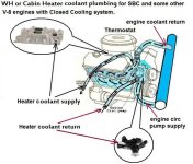
I made this first image to show another member how a water heater or cabin heater would be plumbed in to the engine's coolant path.
However, it also shows the ethylene glycol path to and from the heat exchanger.

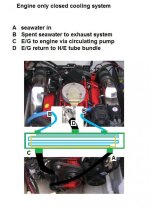
In this second image, I give you a ruff idea of the seawater side of an engine only closed cooling system.
 

Attachments

  • SBC cooling-system 3.jpg
    SBC cooling-system 3.jpg
    81.9 KB · Views: 5,126
  • SBC cooling-system 6.jpg
    SBC cooling-system 6.jpg
    59.4 KB · Views: 123
Last edited:
Hi Rick,
I think that you are regarding my use of the term 'cooling water' to be raw water. Where I use the term cooling water I really mean ethylene glycol in your terminology.
In Australia we do not generally have a problem with freezing so ethylene glycol is not often refered to. So I used the term cooling water to mean all the water within the closed circuit of the HE and engine .
The raw water being the water that is pumped through the tubes of the HE and out through the manifolds.
Does this make my earlier post seem a reasonable way of implementing the plumbing??
 
Hi Rick,
I think that you are regarding my use of the term 'cooling water' to be raw water.
Yes, I was!

Where I use the term cooling water I really mean ethylene glycol in your terminology.
I believe that the term is accepted world wide.

In Australia we do not generally have a problem with freezing so ethylene glycol is not often refered to. So I used the term cooling water to mean all the water within the closed circuit of the HE and engine .
In my opinion, a closed cooling system is rather pointless if you do not plan to use Ethylene Glycol. The PH balance of plain water is certainly against us.

The raw water being the water that is pumped through the tubes of the HE and out through the manifolds.
Yes... now we agree!

Does this make my earlier post seem a reasonable way of implementing the plumbing??
As to your question.... nothing on my end changes.
You'll still need the T-stat housing that I've suggested.

I'll ask again... does your kit not include all of the necessary parts?

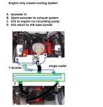
Here's another style of H/E with a single seawater outlet showing how the T diveter is used to divide the spent seawater equally between exhaust manifolds.
 

Attachments

  • SBC cooling-system 7.jpg
    SBC cooling-system 7.jpg
    63.3 KB · Views: 92
Hi Rick,
I am buying my HE through an internet purchasing agent. this way I do not have to worry about tax's, postage ect. on a fairly heavy item. It is a model #MDA91036 supplied by (Marine Direct Australia) and is very simmilar to the 'Monitor Products' range of HEs. MDA probably source the HEs from them in the US. It is 21" long and has an auxillary "saddle tank" with two 1" hose outlets, one at each end. Presumedley these are connected to the exhaust manifolds. A filler/pressure cap is mounted in the centre.
The main body of the HE has one top mounted 11/4" hose connection.
At the opposite end, at the bottom is a further 11/4" hose connection.
the other end at the bottom is a 11/2" hose connection, I would assume this is for the raw water inlet from the impeller pump.
As far as I have been told there are no other fittings or T-stat unit supplied as this is a generic HE which can be adapted for any special application. As in my case where I need to mount it along the engine.

I have not been supplied with any installation Instructions, I guess these come with the HE. there are about 15 different models in the range.

Looking at the detail of the Volvo "closed cooling system" T-stat (lower Housing and Upper Housing) on page 2-15 of the SELCO 2003-12 repair manual for the V8 GXI-F engine, there is shown only one outlet port in the upper hosing above the T-stat which appears to take water from the T-stat when at running temp. and presumedly takes it to the bottom of the HE. The other port is in the lower hosing and I assume is fed with water from the HE
None of the other out/inlet hose connections used with the raw water cooling system are incorporated into this 'closed cooling' T-stat housing.
The actual T-stat fits to the lower housing and controls hot water coming up from the top of the engine just like in the raw water system.
That's why I figured that it was possible to use the existing T-stat housing and maybe just block off the unwanted ports.
 
For this conversation as to avoid any confusion...., may we used "seawater" to describe ocean/lake/river water..... and use "coolant" to describe ethylene glycol?


Here's what I've found for your model #MDA91036 heat exchanger.
Does this look correct to you????

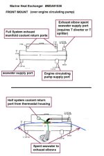
p33b.gif


If so, judging by the twin coolant return ports, this appears to be for a Full System.
The twin return ports would be required for a Full System...... one for each exhaust manifold coolant returns.
(elbows are always seawater cooled... regardless of the cooling system... raw water, Half or Full closed systems)
Unless you are doing a Full System (and you will not be able to with 1pc manifolds), I think that you bought the wrong system!

In the upper image below, I show you how this would be plumbed regarding the seawater pump supply port connection to the H/E, the engine circulating pump supply connection to the H/E (i.e. a suction port), etc.

In the lower image below, I've shown what would be needed for a Half System.
With your 1 pc SS exhaust manifolds, the spent seawater would route to each of them...., not to elbows!
 

Attachments

  • HE for Volvo Penta full system.jpg
    HE for Volvo Penta full system.jpg
    52.5 KB · Views: 128
Last edited:
I'd recommend using a 50/50 mix of ethylene glycol and (preferably) distilled water on the "fresh water side" for two reasons...
1) 50/50 mix is a more efficient heat transfer medium than just plain water
2) commercial 50/50 mixes usually include corrosion resistant additives
 
Thanks Rick for your continuing connection to my problem,

I did ask for advice from "Marine Direct Australia" and their tech advisor (in the US I believe) agreed with me that the MDA91036 was a good choice.
I was informed it was suitable for 'block only' cooling on my 5Lt. V8.
I chose the 41/8" dia. X 21" so as to give me a bit more cooling capabillity at high power.
The 5" dia. HEs which are also available are for FWC according to the data.

Thank you for going to the trouble of drawing up the coolant and seawater circuits.
Your circuit for 'Half System" is what I will be using. I would think that I would connect up the two coolant return ports with a 'T' piece and connect a single hose to the thermostat housing. The seawater return would be connected via a 'T' piece to the two SS manifolds.
The suppliers have even agreed to fit 1/2" feeder hose connection to the HE for connection of a resevoir bottle so that I can mount the assenbly below the top of the engine and avoid air problems.
All I need now is to try and avoid paying out another $800 for a T-stat housing, which is more than 60% of the whole HE assembly!!!!
The problem seems to be that there are fewer suppiers of the full range of Volvo parts compared with the large available choice for Merc parts.
You mentioned in an earlier post that 'T' connections should be avoided and that "Y" connection are much prefered.
From the point of view of fluid flow turbulance the "Y" will give a much better flow rate.
I will try to locate some, otherwise I will have to fabricate them.
 
.........................

Thanks Rick for your continuing connection to my problem,

I did ask for advice from "Marine Direct Australia" and their tech advisor (in the US I believe) agreed with me that the MDA91036 was a good choice.
I was informed it was suitable for 'block only' cooling on my 5Lt. V8.
Do you have a GM 5.0L V-8..... or a Ford 5.0L V-8?

I ask because if the company thought that your engine was a Ford 5.0L, they may have suggested a Heat Exchanger with twin coolant inlets due to the Ford style T-stat housing similar to this one.

images


If GM 5.0L V-8, and for the correct Half System with a single coolant return port, you need this style.

images


I suppose that you could use one like this if you keep the twin return H/E.
images

I chose the 41/8" dia. X 21" so as to give me a bit more cooling capabillity at high power.
The 5" dia. HEs which are also available are for FWC according to the data.
I am not understanding that one.

The term FWC for some means Fresh Water Cooling (one of my pet peeves), and is used in a misnomer fashion to describe a Closed Cooling System.
This has been carried over from years ago when Keel Coolers were used.
There's nothing fresh about Ethylene Glycol ..... ya can't drink it, ya can't wash up in it and ya can't cook with it! :D

Although a great deal of the Marine industry does use the term FWC, technically these are Closed Cooling Systems!

Thank you for going to the trouble of drawing up the coolant and seawater circuits.
Your circuit for 'Half System" is what I will be using. I would think that I would connect up the two coolant return ports with a 'T' piece and connect a single hose to the thermostat housing. The seawater return would be connected via a 'T' piece to the two SS manifolds.
As I suggested and illustrated, this must incorporate a diverter or splitter... otherwise the flow to each manifold may not be equal.
Unequal flow may cause one side to run very hot.

The suppliers have even agreed to fit 1/2" feeder hose connection to the HE for connection of a resevoir bottle so that I can mount the assenbly below the top of the engine and avoid air problems.
You should not have a problem purging air from the system.
The #MDA91036 heat exchanger mounts at the front of the engine elevated above the Circ Pump.

The actual thermostat will have an air bleed hole in the flange.

All I need now is to try and avoid paying out another $800 for a T-stat housing, which is more than 60% of the whole HE assembly!!!!
http://www.ebay.com/sch/i.html?_fro...+housing&_nkw=sbc+thermostat+housing&_sacat=0
 
Last edited:
Hi Rick,
My Volvo 5Lt V8 uses a chevvy small block.

{I chose the 41/8" dia. X 21" so as to give me a bit more cooling capabillity at high power.
The 5" dia. HEs which are also available are for FWC according to the data.
I am not understanding that one. }
I used the term FWC to mean "Full Water Cooling" (block and manifold) a term which I have seen used on other forums.
I guess the problem is that between the US, Europe and other countries the abreviations differ widely and can certainly cause confusion.

If GM 5.0L V-8, and for the correct Half System with a single coolant return port, you need this style.

images


This style of T-stat return port is what I believe I require.

{The suppliers have even agreed to fit 1/2" feeder hose connection to the HE for connection of a resevoir bottle so that I can mount the assenbly below the top of the engine and avoid air problems.
You should not have air purging problems.
The #MDA91036 heat exchanger mounts at the front of the engine elevated above the Circ Pump. }


On my Monterey there is not much head room in the engine bay when the top cover (and seating) is fully closed down and secured.
That's why I chose to take the route I have and mount the HE along the Starboard side of the engine bay where I have plenty of room.

In looking at all the T-stat outlet fittings on the Ebay link you provided, and the prices of the units. I still can't get my head around why Volvo have such a complicated two part housing arangement with the thermostat mounted into the top of the lower unit. The upper unit containing just the single output port to the HE and costing $800.00
In the Seawater cooled engine as it is now, the thermostat sits into the main block casting with 'O' ring and is secured by the top cover which has the two outlets to the manifolds and the main seawater inlet.
So I am going to buy one of the swivel units on ebay and see if I can fly with it!!


Hi Rick,
My Volvo 5Lt V8 uses a chevvy small block.

{I chose the 41/8" dia. X 21" so as to give me a bit more cooling capabillity at high power.
The 5" dia. HEs which are also available are for FWC according to the data.
I am not understanding that one. }
I used the term FWC to mean "Full Water Cooling" (block and manifold) a term which I have seen used on other forums.
I guess the problem is that between the US, Europe and other countries the abreviations differ widely and can certainly cause confusion.
Apparently so. Our communication has been somewhat complicated and difficult.

If GM 5.0L V-8, and for the correct Half System with a single coolant return port, you need this style.

images


This style of T-stat return port is what I believe I require.
This is NOT a return port!!!!
This is the Thermostat Housing of which directs the coolant FROM the engine TO the heat exchanger after it exits via the Thermostat.


I think that we are having trouble with our communication, so if you'll please excuse me... I'm going to leave the rest of this up to you.
I do wish you the best luck with your installation.


.
 
Last edited:
I was using the term "return port' to imply that the coolent was being returned to the HE from the engine for re-cooling by the HE
 
My SS exhaust manifolds have now been fitted and I am in the process of plumbing my HE
These manifolds are very impressive, however they are now made in China and of course the attention to detail is obvious by it's absense!!
I have sorted the configuration of the closed-circuit-system thermostat which works so as to bipass coolent back to the top of the engine coolent pump via a spring loaded plate on the bottom of the thermostat which then closes at 70deg C.
I do have one concern, based on advice from new found friends in the water area I am in, I have decided to fit a RW filter/strainer.
Must this strainer be fully below the level of the raw water intake pipe so as to allow the RW pump to be always primed??
I just cannot find a way of getting the Strainer low enough whithout a major re-routing of cabling.
 
Last edited:
.........................

I have sorted the configuration of the closed-circuit-system thermostat which works so as to bipass coolent back to the top of the engine coolent pump via a spring loaded plate on the bottom of the thermostat which then closes at 70deg C.
Who is suggesting that this is necessary on a SBC?

I do have one concern, based on advice from new found friends in the water area I am in, I have decided to fit a RW filter/strainer.
Must this strainer be fully below the level of the raw water intake pipe so as to allow the RW pump to be always primed??
Pictures?
 
Hi Rick, happy new year and all that.
No one has suggested it is necessary, it is just that the Volvo thermostat and housing assembly (if I were to buy it) allow for this.
I have machined a housing from a 100mm billet of alluminium.
I guess this approach does greatly reduce engine warmup time, I have tested the assembly and it works very well.

I will take a pic tomorrow, the problem is there is very little room at the front of the engine bay, with cables from the battery and controls crossing across the front of the engine.
 
I've seen the by-pass used on the Ford 460 and the BBC, but I don't recall having seen one used on a SBC.

Volvo does show a by-pass being used on the 5.0GXi-BF, 5.7Gi-BF, 5.7GXi-CF, 5.7OSi-AF, 5.7OSXi-AF.
I'm willing to bet that either the circ pump fitting (suction side) or the T-stat housing outlet is restricted.


If non-restricted, it's possible that it may affect the coolant supply/return for a cabin heater or water heater as well.


.
 
Hi people,
It's now about 9 months since I received much help from this thread on retrofitting closed loop cooling to my 5.0Lt V8 Volvo engine. I did in fact fit a set of one-piece SS extracter exhausts (reccomended here) to the engine in Jan which greatly reduced the weight on the back end and improved power by possibly about 20 hp. They are a really great improvement if you can justify the cost. They also of course illiminate the problem of exhaust cooling which makes everything much simpler.
I now have the raw water heat exchanger and an oil cooler which I am considering fitting in the next few weeks.
However the owner and friend who rents the pen next to me had his starboard engine (diesel) overheat and stop a few weeks ago.
It seems that where we are on the lower reaches of the Hawkesbury river north of Sydney the pollution from runoff is causing an enormous amount of black weed growth which blocked up his filter.
Now the heat exchanger and oil cooler I have are fitted with may small-bore tubes for the raw water.
Should I fit a filter and perhaps even a flow indicator to avoid weed blockage problems???
 
Last edited:
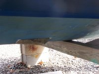
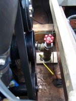
The area I boat in has some years where large masses of "eel grass" grow and break free and end up in most filters. If you don't inspect and clear filters ( some times daily) you will get an overheat. I've avoided this problem by going to an external wedge shaped scoop with an external filter screen on it. In order to get a good water flow and keep out smaiil weeds, I went one size bigger on the scoop. Pay attention to the hole size on the screen ( its listed online with the specs) as well as the max size of the water inlet. Scoop is sized per inlet line diameter, i.e. for 1.25" dia, etc, size. Go one size up. Some units haVE removeable S/S inlet screen... These are better. Some units have a cleanout port as well. REcommend two fast thin coats of zinc anti fouling spray applied per can instructions. I pull my screen ( 4 nylon screws) every spring and clean off all old zinc paint and reapply. This setup allows a quick easy fresh water flush at anytime and avoids waterneck issues on drive permanently.

Thru_Hull_WaterInlet_2257.jpgThruHull_rawwaterinlet_internal_2266.jpg
 
Back
Top