Logo

In over my head with 5.0 distributor!

wes910

Member
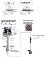
I have a 02 mercruiser 5.0 gen 2 carb model. I had to replaced the intake manifold, Like a dumb dumb when I pulled the distributor I did not mark anything. Reading threw the service book, It tells me to align all the marks which I dont have. I have no idea where to start.

- I need to know once I get the number 1 on TDC where should the rotor orientation be for the 1 spot on the cap?
- Also when putting plug wires back on the cap do the numbers correspond to the cylinder numbers?
-I cant find the timing tab on the block
 
Cap should have the numbers on it
UntitledW9_zpsc64a3e98.jpg
 
the manual, do you have the mercruiser one? would need the engine serial number.
post some pics using photobucket.com..need to see the engine, carb, dist
 
Wes, before you begin, it will be imparitive that you bring the #1 cylinder piston up to near TDC, but on the Compression Stroke ONLY since #1 TDC comes around twice per each full engine cycle.

Actually... stop the piston just prior to exact TDC.... maybe 6 degrees or so prior.

Now with the distributor's rotor aiming towards the #1 cylinder.... (or perhaps towards the #1 plug wire cap socket if the cap is marked), insert the distributor housing.

Keep in mind that the distributor "driven" gear must mesh with the camshaft "drive" gear.
It may require several attempts, and even moving the oil pump's slotted drive shaft a bit.
Once these are indexed, the housing will drop into position.

Once installed, place a spark plug into the #1 plug wire.... and give it good negative contact with the engine.

Watch out for fuel vapors because we're going to make a spark soon.

Snug up the clamping bolt some... but not too tight.
Now power up the ignition.
Quickly rotate the housing from a CW position in a CCW direction.
When you see a spark event, this will simulate #1 firing.
Do this several times until you get a good feel for it.
Stop rotating when you see the spark.
Now snug the clamping bolt down a bit more.

Now the engine should fire up, and be ready for you to set BASE advance.


,
 
the manual, do you have the mercruiser one? would need the engine serial number.
post some pics using photobucket.com..need to see the engine, carb, dist

I have the clymer book. heres my sn 0m098856

Also when rotating the cap to see a spark does the engine need to be spinning? or just the key on?

The book says to get to TDC I need to remove the plug and spin tell I feel pressure with my finger over the spark plug hole. I having a hard time locating the marks on the balancer and finding the tab on the block
 
.........................

I have the clymer book. heres my sn 0m098856
Toss the Clymers in the recycle bin, and get yourself an OEM work shop service manual.

Also when rotating the cap to see a spark....
You won't be rotating the cap..... you'll be rotating the entire distributor housing... cap included.

.... does the engine need to be spinning?
No.... the crankshaft will be stationary.

or just the key on?
With the igntion ON..... you'll be simulating one spark event as you rotate the housing in the CCW direction (oposite of the internal shaft direction).
Key word "simulating".

That's the objective...... to create one spark event to see where you are prior to a start up attempt!


The book says to get to TDC I need to remove the plug and spin tell I feel pressure with my finger over the spark plug hole.

Well.... that is somewhat incomplete information and could be elaborated on some!

TDC comes around twice per one complete engine cycle.
A complete 4 stroke engine cycle involves two crankshaft revolutions.

Your job is to find TDC C/S... of which can be determined with the finger over the #1 spark plug port.

When you feel the cylinder pressure build..... the #1 piston is moving upwards, and indicates that both intake and exhaust valves are closed.
This can only occur during Compression Stroke when you will feel the cylinder pressure build against your finger.
(during an exhaust stroke, or during an intake stroke, the repective valves are open)

Stop just prior to TDC.... and you're very close.


I having a hard time locating the marks on the balancer and finding the tab on the block
It may be a simple pointer only at the cover.

The balancer should be marked off in addition to the TDC marking.
If not.... you'll need to use a High Quality digitally advancing timing light in order to view the progressive and TA.


.
 
Last edited:
why do you folks INSIST that the rotor point to the number one cylinder ?? that is total crap !! when the piston is coming up on the compression stroke.....stop it just prior....about 5 to 10 degrees prior. you can then install the distributor.......WITH THE ROTOR POINTING IN ANY DIRECTION YOU WANT AS LONG AS YOU INSTALL THE SPARKPLUG WIRES IN THE CORRECT FIRING ORDER AND THE DISTRIBUTOR IS FULLY SEATED. there is absolutely NO MECHANICAL RELATIONSHIP that requires the "rotor to point to the number one cylinder".....IN ANY ENGINE.
 
.........................

why do you folks INSIST that the rotor point to the number one cylinder ?? that is total crap !!
For some of us mechanics there is a reason for doing so.
However, it is not a deal if/when we do not!

I'm curious..... why are you so concerned if this suggestion is made?


WITH THE ROTOR POINTING IN ANY DIRECTION YOU WANT AS LONG AS YOU INSTALL THE SPARKPLUG WIRES IN THE CORRECT FIRING ORDER AND THE DISTRIBUTOR IS FULLY SEATED. there is absolutely NO MECHANICAL RELATIONSHIP that requires the "rotor to point to the number one cylinder".....
I fully agree!
The distributor can be indexed in as many positions as there are "driven" gear teeth.
The cap towers can be wired in one of 8 possibilities, as long as the firing order is observed.

 
Last edited:
the reason why it concerns me so much.....is that so many people do not realize that the rotor pointing to number one hole is so silly , when they should be focusing on "walking" the rotor to to get it to drop into the position to align with the placement of the wires already on the cap. if that is not possible.....it is so much easier to just get the engine to come up on the compression stroke, and stop it just prior to tdc. then they should focus on getting the distributor to SEAT fully with clearance for the vacuum advance, if it has one........then install the wires in the correct firing order. trying to do this....AND getting it to point at the number one cylinder.....serves no purpose, and just adds an axtra atep for an already confused repair person.
 
.......................

the reason why it concerns me so much.....is that so many people do not realize that the rotor pointing to number one hole is so silly ,
Silly to you... but perhaps not silly to others.


when they should be focusing on "walking" the rotor to to get it to drop into the position to align with the placement of the wires already on the cap.
And what if the cap wiring already allows for the rotor to be physically aiming towards # 1 cylinder while at TDC C/S?


if that is not possible.....it is so much easier to just get the engine to come up on the compression stroke, and stop it just prior to tdc.
Agreed.... this part is easy.
So is indexing the oil pump drive so that the distributor will drop into position with the rotor aiming towards #1 cylinder while at TDC C/S.


then they should focus on getting the distributor to SEAT fully with clearance for the vacuum advance, if it has one........
Marine engines do not use vacuum diaphram advance.
Perhaps your experience is more so with automotive, and you may not be as well experienced with Marine Engines ...... I don't know.


then install the wires in the correct firing order. trying to do this....AND getting it to point at the number one cylinder.....serves no purpose, and just adds an axtra atep for an already confused repair person.
Confused people are better off when they ask for assistance... such as what Wes is doing here! His thread title implies that he's a bit over his head! That's why we're here... to help him.

Aiming the rotor towards the physical location of #1 cylinder has been used for years. It's nothing new at all.


On a truly technical basis, you are correct and on that note I don't necessarily disagree with you.
The ignition distributor, the cap, the plug wires, the spark plugs, etc... don't give a rip how they are indexed, as long as the correct firing order is observed... and as long as the ignition timing is correct..... all will work well.


None of these components will know the difference, unless you tell them! :D

An exception to this would be an "Odd Fire" engine, such as the little Buick V-6 of years ago.
This ignition distributor housing, rotor, plug wires, etc... must be indexed correctly and according to the manufacture.
You DO NOT arbritrarily change this one without causing engine damage. Bad Ju Ju!


.
 
Last edited:
I hope this is a Chevy 5.0, not a Ford 5.0? or the firing order, and procedure would be different.

The reason for indexing the Dizzy, and firing order as shown on some diagrams where the Dizzy cap hold down bolts are located also, is so that the spark plug wires fit where they belong without disturbing them, for some semblance of order.

Oops! Sorry, I see this is an 02' - 5.0, So it has to be a Chevy motor, they discontinued using Ford 5.0 motors years before this.
 
Wes, you can do this.... you just need a bit of patience. ;)

Note that your Merc EST ignition system will need to be in BASE mode while setting the timing advance.


Whether you want to aim the rotor towards the physical location of #1 cylinder or not....... here's an image that I put together for you.
It may help you to understand what's involved.

If you do not care, such as Crankbait, let the ignition distributor drop in where-ever it wants to, and wire the cap accordingly.
It will allow for ignition timing just the same.

If you do care, such as I do, note that the main obstacle will be the oil pump drive shaft "slot" and the "blade" within the driven gear that drives the shaft.
You may need to rotate this shaft a bit in order for the distributor to drop down in.
Try to drop it in... rotate a bit more..... try to drop it in again..... rotate again if need be......, and you'll eventually get it.

This shaft can be easily rotated with a large straight slot screw driver.

Note that when the two gears begin to mesh.... you will see some additional distributor shaft rotation as the housing fully drops in. (helical gear cut)
 

Attachments

  • oil pump drive distributor install.jpg
    oil pump drive distributor install.jpg
    50 KB · Views: 56
Last edited:
Thank you I got all all of that and got it fired up!!!!!.... Now on to base timing...hows this done? The balancer only has one line on it
 
Thanks for the info, I do have a couple more questions. I went threw and set the timing, The purple and white wire I found in the loom. Once done does it not get pluged back into anything? It was just sitting there in the loom. Also once its running its sounds fine and runs good with smooth working of the throttle. However if blip the throttle I got a back fire threw the carb is this normal when working the throttle quick or is it something else?
 
This is happening because your timing is too advanced and you can retard it by losing the distributor bolt and turning the distributor anti clock wise to advance and clock wise to retard the time.
 
This is happening because your timing is too advanced and you can retard it by losing the distributor bolt and turning the distributor anti clock wise to advance and clock wise to retard the time.


Hey Flash,
News Flash....lol

This post was from 2014.

May want to look at the dates so your not responding to a 10 year old post...
 
Back
Top