Logo

plastic nuts for alignment

Mike29

Contributing Member
When doing my alignment do I need to loosen the motor mount bolts or can I turn the plastic nuts with the bolts tight? Is there a special spanner to fit the holes in the plastic nuts or can I turn them with a stubby screwdriver?
 
I found it online ...loosen lag bolts and make adjustment using a tool or 3/8" rod thru the plastic sleeve. Any tips appreciated.
 
Just did mine after changing cutlass bearings. After 10 years of no movement mounts turned really hard. Eventually some cracked using the rod method. I bought a tool on line to replace the rod. It was a large 3/4" drive socket that had been turned and cut so that it fit into the 4 slots on top of the plastic sleeve adjustment on the mount. As I recall it was around $50. Anyway, this was a great help and they could now be turned without cracking. But it still was difficult.

In the end I bought new mounts that turned very easily. I changed them one at a time, without jacks. Disconnect your prop shaft flange. Remove the lag bolt on the mount you want to replace. Raise the two mounts on the corners nearest and lower the one on the corner opposite. When you can slip something under the one you want to replace, the weight is all on the other three. Just loosen the clamp that holds it to the motor bracket and slide it out and replace it. Once you have one of them replaced (and it adjusts easily) it becomes increasingly quick and easy to do the rest. Because the mounts can pull down, as well as adjust up, it is really not that difficult to "rock" the motor such that the weight is lifted from one of the mounts.

I'll let others comment on how to actually (correctly) adjust the engine to the prop shaft flange. It should be easy but I managed to make it rather time consuming so perhaps a good response will teach me the "right" way!

CaboJohn
 
I don't remember but there are several sources out there if you search under "Crusader mount adjusting tool" or any such description. There is a Crusader part number on it of #22165. All the pictures I saw look about the same so I would think any of them would work.

CaboJohn
 
a bit late but here goes...if you use the thru rod, don't loosen the lags too much as they will "rise" into the space the 'rod' needs...and don't try to spin the nut using a screwdriver (or anything else) when its inserted into only one hole....it will snap, especially the older white ones.
 
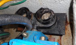
Is there a special procedure for adjusting the mounts that have two of the plastic adjusters for raising or lowering the engine? Adjust both about the same amount so the pressure on each is the same? Note how someone has already broken the plastic cap on the right.

How about moving the engine left or right. Is the engine mounting bracket normally slotted to allow some movement or is the engine slid on the rod section of the mount that goes into the engine? Does that nut and bolt near the middle of the picture somehow clamp the engine to that rod?
 

Attachments

  • double engine mount.jpg
    double engine mount.jpg
    72.6 KB · Views: 37
Ideally, you want to keep the dual adjuster parallel to the stringer service, so yes, adjust both threaded adjusters equally...with the broken adjuster, it may be easier said than done.

for left right adjustment, the adjusters are fixed to the stringers. What you called the rod is formally called a trunnion. they to are 'fixed'. The engine/gear slids left to right on the trunions and the "nut and bolt" cause a clamping down action on the trunnion to stop further movement once adjusted.
 
You can correct the angular alignment of the engine to the prop shaft by articulating the dual adjusters on the vee drive independently, ie: if your shim stock is unequal from left to right, but equal from top to bottom.
 
Last edited:
Mark...never to late for good advice. I have the older white mounts so won't attempt this until I get the "tool"....Thank You John. Will PB blaster hurt the white plastic mounts? Thought I should spray the bolts in prep for the alignment.
 
PB won't hurt it but, in my experience, won't help much...

What we have found happens is that the threaded portions of the mount corrode and bind the white plastic adjuster...due to the surface area, the friction provides a lot of resistance to the adjuster's movement and the plastic always fails first...so far, on the few I've replaced, covering the threaded area with anti-sieze and working it throughout the threaded region is the best approach...
 
Ideally, you want to keep the dual adjuster parallel to the stringer service, so yes, adjust both threaded adjusters equally...with the broken adjuster, it may be easier said than done.

for left right adjustment, the adjusters are fixed to the stringers. What you called the rod is formally called a trunnion. they to are 'fixed'. The engine/gear slids left to right on the trunions and the "nut and bolt" cause a clamping down action on the trunnion to stop further movement once adjusted.

OK, thanks for the reply.
 
You can correct the angular alignment of the engine to the prop shaft by articulating the dual adjusters on the vee drive independently, ie: if your shim stock is unequal from left to right, but equal from top to bottom.

Sorry but I don't understand. Can you please elaborate and also what do you mean by "shim stock". They are V drives...could you tell that just from the photo...or do only V drives have the dual adjusters?

Erich
 
Back
Top