Logo

Mercruiser 470 pertronix wiring question

Teamcrush

Member
I have a 1981 Mercruiser 470 with 760 hours which I have owned for the past three years. It was not abused (but not maintained) when I got it, but over the past 3 seasons I have upgraded most of the recommended systems including, alternator, starter, riser, thermostat, cooling systems flushed and pertronix 1146a with 40k 3 ohm coil. The engine runs fine except after 45 minutes of run time the engine misses and backfires and will eventually die. I can run for half an hour no issues, only at forty five minutes. I'm confident in my fuel system because I ran an auxiliary outboard off the same tank. After lots of reading here, I suspect I may not have the pertronix kit wired to the coil incorrectly. The more i read the more confused I become. This is how it is wired now

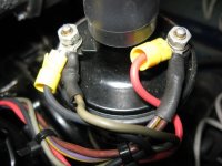
negative has black from the pertronix and grey from the tach(?)
positive has red from the pertronix, purple with yellow stripe, and a more redish/brown shade of purple.

Both of these two purple wires are terminated together from the factory. the purple with yellow goes to a (solenoid looking thing) beside the starter and the more redish/brown shade of purple wire goes directly to the choke. I am not sure if this is wired correctly but it runs (for 45 minutes). I want to know do I simply cut the more redish/brown shade of purple wire away and carry on? Or, do I cut it out and have to wire in another regular wire between the choke and the coil. Or, do I have to remove more redish/brown shade of purple wire and run another wire from a keyed source to the positive side of coil? Man, I am not only confused - confusing too!
Thanks in advance teamcrush
 

Attachments

  • 005_zps7527d162.jpg
    005_zps7527d162.jpg
    51.5 KB · Views: 2,732
A co-worker had very similar symptoms on his boat. He replaced a lot of ignition system components and gave boat rides to at least two marine mechanics. In the end it was his fuel anti-siphon valve. Located between the outlet of his fuel tank and the beginning of his fuel line, it was partially clogged and couldn't deliver enough fuel to keep the engine going at cruising speed.
 
Hi DJR,
I installed anti-siphon valves to both engines when i added the auxiliary motor to the fuel tank (off the water separator) so valves are not very old. I can easily remove and check, thanks for the tip.
 
First is your coil,

The point ignition had a resistance wire biult into the wiring harness. It is the wrapped up in the harness and is about 3 feet long and has a resistance of about ~ 2 OHMS. If you installed a coil with a internal resistor you have doubled the resistance,

A point ignition uses a non internal resistance coil. A electronic (FACTORY) ignition has a internal resistance.

So what is going on is you now have ~6 ohms resistance so the voltage reaching the coil is far less than it should be. It should be when running normally ~ 10 +/- volts DC........You would think it would be the battery voltage but that is what the resistor does it reduces the running voltage from ~ 13 volts when running and charging down to ~ 10 +/- Volts DC. You most likley have ~ 6-8 volts DC when running now.

If you have the original coil I would swap it out and re test. If this corrects your issue then purchase a new non internal resistance coil from any automotive supply.............I can guarentee you are not getting "40,000 volts" out of that coil...............

From what I read for installation you have it wired correctly.

AND NO DO NOT CUT ANY WIRES!!!!!

The reason you have two purple wires is one is for power during cranking and the other is for power when running!!

What can be disconnected for testing is the grey wire (tach lead) to see if your tach is faulty...........and possibly causing a issue with the ignition.


Also what is your running temp for the motor? Is it getting HOT? over 180 degrees?
 
Last edited:
Hi Kghost,
When I installed the pertronix kit I also changed from the original coil. I now have the pertronix coil 3ohms 40K volts which I believe has an interenal resistor. When I run I have never seen the temperature go beyond 175 degrees - stays at 160 degrees 95% of the time. I will disconnect the tach next time out to see if it could be the tach but if I have the coil with a built in resistor should I cut the brownish purple wire, would it run if I cut it and left the purple with yellow stripe?

I will post picutres this evening of the brownish purple wire going into the choke and the other of the purple with yellow stripe going beside the starter.
Thanks, Teamcrush
 
No do not cut any wires

What I said is you have the wrong coil (the pertronix coil is wrong)...........Your ignition already has a 2 ohm resistor (wire) within the purple wire coming from the wire harness connected to the + of the coil. (the brownish purple wire)

You need two wires to the + side of the coil, one when you are cranking the motor over to start it (purple with yellow stripe) and the other takes over when you return the key to the run position (ignition on).

Your original coil did not have 3 ohms resistance built in...

Swap back to your original coil and retest.
Also disconnect the tach and retest.
 
Last edited:
I do not have the old coil. I will buy a new one, can you tell me exactly the type to buy and a suggested brand please. I like this plan, thanks for the tip.
 
Last edited:
If you use the stock coil you will need another source of power to the module ballast voltage will burn it up. Tap another wire into the ignition wire from the switch before the resistor wire will get you battery voltage for the module.

This is not so..............


He does not have a balast resistor AGAIN I will repeat myself

He has like every other Mercury Marine GM point ignition, a resistor WIRE biult into the harness. This wire is ~ 2 ohms.

The stock original coil was not or did not have a internal resistor biult into it or a balast resistor attached to the coil END OF STORY.

So what is needed is the stock coil, ANY AUTOMOTIVE PARTS STORE will have a point ignition coil available or buy one from a marine supply store.

If you know someone who works on cars maybe they have on you can borrow to test and if it solves your problem then buy one....

Agian any point ignition coil "should" be a NONRESISTANCE coil type.

All point ignitions from the day either had a resistyance wire (GM) or a balast resistor (FORD AND CHRYSLER).........
 
If the power to the coil has a ballast resistor just get the stock coil for that motor. The pertronix requires 12 volts so you cannot use the coil pos for the module as low volts may burn up the module. If the pertronix coil in internall resisted it requires 12 volts you can also just run a jumper wire before the ballast resistor or just a hot from the ignition switch direct to the coil and module bypassing the ballast resistor just disable that circuit. It just seems to me someone hacked in some wiring the only things you want running on the ignition switch is the coil and module the shift assist if it has one just interupts the coil neg signal. I couldnt find the installation instructions for the 1146A.

In order for him to bypass the resistor wire he needs to unwrap the wiring harness, find the resistance wire, follow it back to a multi wire junction and remove it and replace it.........I doubt that is gonna happen...............
 
kghost, I know he needs 12v just for starting, but doesn't he need a full 12v non-resistor wire to run the Pertronics? I don't remember which, but I tapped into one of my switched 12v wires for Pertronics ignition on my old Celebrity cuddy.
 
Yes If he disconnects the purple/brownish wire he describes and runs a new wire form a 12 volt connection that is only on when the key is on that would work with his current coil.
But he may not understand or know where to connect it..............

If this is the way he would want to do this then he must undo/unwrap the wiring harness, find the resistor wire and follow it back to the multi wire junction and remove it and connect a new wire at that point and place and run it to the + coil connection........if it is to be a clean seamless rewire.

This is how I would do it.

But until then he can easily swap the coil for the correct one and see if this corrects his problem.

It may not even be the cause to his issue but it is for sure not correct anyways.......
 
Last edited:
Then what is your solution? Again explain what is the difference between a resistor wire and a ballast resistor.
http://www.ebay.com/itm/NEW-FORD-FI...arts_Vehicles_CarParts_SM&hash=item3a895ebffa
They both do the exact same thing! I could not find the installation instructions for that paticular module but they clearly state do not run on ballast voltage if under a certain voltage 12+volts is allways better.

The difference is the ballast resistor is out in the open and easily accessible

The resistance WIRE is buried in the harness and is three feet long and folded over on itself and is NOT copper it is some other material..
 
Yes you do need the start circuit. Other wise the motor will only turn over until he lets the key return to the run position. This also occurs when the on starter solenoid has issues for this circuit.............The way to avoid this is to change the key switch so the key switch controls the cranking and running voltage. This is the way the thunderbolt electronic ignitions work, crank and run are controlled thru the ignition switch and not the starter solenoid.
 
009_zps0ad64cbb.jpgThis is the choke, see the brownish purple wire that goes directly to the positive side of coil.
008_zpsd413be1e.jpgthis is the solenoid looking thing beside the starter where the purple with yellow stripe wire starts before it is attached to positive side of coil.

Kghost say's;"

"In order for him to bypass the resistor wire he needs to unwrap the wiring harness, find the resistance wire, follow it back to a multi wire junction and remove it and replace it.........I doubt that is gonna happen...............''

Yes, this is true!

So this is what I am going to buy and test
http://www.iboats.com/mall/partfind...gd_poid=111745&gd_row=11&session_id=569416713

In your opinion would it be better to wire a 12 volt keyed source to the coil and keep the pertronix coil or just go with the stock coil? Is there a 12 volt keyed source on the block or does it have to come from the dash?

Thanks for the information and the informative debate!
team
 
Hi Kimcrwbr1
So we all agree it is wrong right now - but runs fairly good. I am going to try running the stock coil next time out to see if it fails after 45 minutes. I can't believe how well it starts and idles if the resistance is so high. After I test the stock coil I am going to get a keyed power source attached to the coil and delete the resistance wire, swap back the pertronix coil and test again. Does this sound like a logical route? When all is tested I will report back - may take a few weeks. I ordered a stock coil from the auto parts store today, will have it installed this weekend. I don't see the voltage regulator on the diagram, where is it located?
team
 
If the schematic it 100% accurate, then there would be two purple wires connected at the choke and one is 12 volts the other would be the resistor wire going to the coil, In other words the choke connection would be the "junction" I refered to earlier.

Unfortunatly I do not believe this to be true. It is just a graphic representation of the curcuit. That "junction" is buried in the harness.

But You could add a second wire from the choke purple connection to the coil + and this would work as a 12 volt nonresistor wire. The purpleish brown would need to be disconected at the coil and taped off and tucked away.

One thing, I have never said this would fix your 45 minute issue. I was pointing out what you have now is the wrong set up.

There are many factors we are not sure of, But if the coil is fatiguing due to the current set up then it is possible.
Also you do have some hours on this motor, what I would look at is the distributor shaft wobble when the boat stops runnning. Distributors that are tilted like this one and the inline six and inline small 4 cylinder motors tend to wear the distributor shaft bushings out and as it warms up the shaft begins to wobble more and more and the proper gap is lost between the point cam and the sensor (points and cam when in a stock configuration)
This particular issues does cause the symtoms you describe!!


What needs to be done when the 45 minutes occur is as follows

1, boat dies.
2. check for spark at spark plug and/or coil wire
3 spark yes or no?

4 If no the problem is with the ignition or shift interuptor
5. If yes the it is either fuel or a wiring issue......
6 check the big wire harness connector and make sure it is tight
7 look at dash wiring to ignition switch make sure all is tight.


Not much else I can suggest at this time.

Only saying it dies or wont run after 45 minutes leaves to many questions unanswered.

Need the spark or no spark answered.....

One last thing to look for and has happened to me.
The radiator cap has to seal the resevoir, If it leaks any antifreeze out that anti freeze will drain down directly to number 2 and 3 spark plugs and short them out.....if you see dried traces of antifreeze going to the spark plugs, replace the radiator cap. This happens after a short while of running as the pressure biulds up in the cooling system.
 
Last edited:
I don't see the voltage regulator on the diagram, where is it located?
team

If you swapped out the regulator to a regular altenator then it will not be there any longer. The original set up was a rectifier /regulator and a stator under the harmonic balancer. Bad set up and was plagued with issues.
 
http://www.boatfix.com/merc/servmanl/13/13e4r2.pdf
Are the big wires going to the slave solenoid from the battery to the starter solenoid on the starter. If this is your wiring diagram you definately have wiring issues you need to resolve first. I believe you can just pull key on hot from the alternator purple wire for the pertronix module. Unless there is a diode in the wire from the solenoid to the coil it is telling me the slave solenoid is allways energized. What the slave solenoid is used for is to provide current directly from the battery to the start solenoid. It draws alot of amps the slave coil uses low amps from the ignition switch and energizes the start solenoid to both close the contacts and enguage the starter pinion. I suggest you print out a good wiring diagram and go through everything now so you dont run into issues out there. Those big red wires to the slave are a big red flag to me. I could be wrong maybe Ricardo will give you the advice you need?

There were a few different configurations through out the evolution to the 470............this one looks like it has a ford style slave solenoid. they seem to have the battery cable hooked there. This is ok location for this connection
There were two style starters used, one looked like a normal type chevy starter with a solenoid attached and the other was basically a one wire stater motor with NO sloenoid.
Not sure what he has,

Also in the picture........that small diameter water hose is connected to your regulator.
Also it looks like some rewiring has been done, The red wire connected to the choke is the WRONG color and should be purple if it even belongs there at all.
where does that red wire go from the choke connection?

As you can see there seems to be more questions than answers because previuos boat owners do not follow wiring rules and replace/add wires and use the wrong colors..........so many like to use one color for every connection as they understand what they are doing when they are doing it but anyone who follows them gets confused...........
 
Note to NEW MEMBERS

Please add your location to your profile, this helps us believe it or not, Also you never know one of us may live close enough to actually come help you in person.............
 
The radiator cap is new with no leaks

The starter is the normal type chevy starter with a solenoid attached

"The red wire connected to the choke is the WRONG color and should be purple if it even belongs there at all.
where does that red wire go from the choke connection?"
The red wire you mention is the brownish purple wire which goes directly from the choke to the coil + this must be the resistor wire. I do beleive the wiring has been messed with at point in time. The purple wire going to the choke will be a keyed 12 volt source? This is what I will try after I test the stock coil.

"Also in the picture........that small diameter water hose is connected to your regulator.
Also it looks like some rewiring has been done"
The only wiring which was done in my time is the addition of a one wire alternator. The old stator system wires were deleted.

Location has been profile - Thanks
 
Before swapping any wires.........Now that we know more..................


If the red wire was added to the choke and goes directly to the coil + it is most likely a full 12 volts and NO resistor.

You must confirm this before swapping coils if you do this.

Important info left out..............

If the wire at the coil is purple/brownish is it spliced into that red wire and is it visible?

this is important!! because someone may have bypassed the resistor wire already.


YOU MUST CONFIRM THIS!!

If the resistor wire has been bypassed then you CANNOT use the stock coil.
 
The brownish purple wire leaves the choke and goes directly to coil+, if you look at the wire in the choke picture the flash makes it appear red, if you look at the very first picture of the coil you can see it is terminated together with the purple yellow striped wire at the coil+ in a factory heat shrink jacket. With all your help this leads me to believe it is the restistor wire and the wiring is wrong for this coil. Now the purple wire going to the choke goes into the harness I can't confirm where it goes. If I am correct, this is a keyed 12 volt source. I should splice into this wire, go to the coil+ and delete the purple brownish wire between the coil and choke. I had a very incompetent mechanic do the electrical work for me, since then several of the systems he installed have failed. I have corrected all but this one, as you can interpret from my dialog I am not confident with electrical. I actually beleive the ignition system is wired wrong and the coil gets so hot after 45 minutes the motor dies. I have thought the distributor may have wear. In the back of my mind I was thinking of adding the mallory marine distributor if the problem continues after the ignition gets sorted out. Oh the joys of having an old boat!
 
Coil was removed last season when I hired the 30 year experienced marine mechanic to install the pertronix system, If I recall correctly this is the one -
  • 40,000 volts
  • For use with inductive ignition systems.
  • Black finish for that "stock" look
  • 3.0 Ohm primary resistance value
  • 1146A+40611
I have not checked voltage but I do have a volt meter. If I checked the voltage at the coil can you tell if it is wrong, I can check tonight. Just check the - & + on the coil when running? I did get the hotter plugs after installing the pertronix system as recommended.
 
The factory resistor wire color should be purple. the inner core of the wire is NOT copper stranded like every other wire used, it is SOLID and almost looks like aluminum in appearence.

Is it possible the tech removed the resistance wire and replaced it with a new one and left it out of the harness and did this because you are running a resistered coil????????

I can tell you from my experience, The wire from the coil to the choke should not be exposed....period.
If it is then it has been manipulated before......All wires in a factory harness are wrapped in the harness except pig tail ends not used and typically hang out such as unused grounds......


Remove that wire form the coil and from the choke. Cut the choke end OFF.

Measure the OHMS of that wire (red looking).
Make sure your meter is zeroed and in the Rx1 or Rx 10 scale and the two leads touching each other the meter read 0 or almost 0

Now measure te wire. give us the results........


Inductive Discharge
Inductive-discharge ignitions date back to the earliest points-type ignition systems. In its simplest form, this system uses a set of points to trigger a coil. All coils operate on the same basic principal with a small number of primary windings outside a large number of secondary windings wrapped around a metal core. The positive side of the coil is connected to battery power while the negative side is connected to the distributor points and eventually to ground. The high-tension tower lead directs the output of the coil to the distributor and eventually to the spark plugs. Since points cannot handle a full 12-14 volts, a ballast resistor is used to reduce operating voltage to 6-8 volts and to limit the amount of current passing through the points.
There are generally about 100 times the number of secondary windings to the primary windings in the coil called the turns ratio. When the points are closed, current flows through the coil, charging the primary windings. The length of time that the points are closed is called dwell time. When the points open, the current flow is interrupted and the magnetic field created by the current in the primary windings collapses across the secondary windings, creating a much higher voltage, but at a reduced amperage. Generally, a stock points-type coil can create as much as 25,000 to 30,000 volts. Even though these coils are capable of this, high-voltage street engines generally only require about 8,000 to 12,000 volts to ignite the mixture.
 
Last edited:
Is it possible the tech removed the resistance wire and replaced it with a new one and left it out of the harness and did this because you are running a resistered coil????????

No, because it is terminated at the coil in a factory shrink wrap exactly like the rest of the factory wires. The redhish bronwish purple wire may have changed colour with age and heat? It goes into the choke with a straight purple wire (origin unkown) in a double wire clamp that simple clips off the choke. I will unclip it, then remove from coil and test the ohms tonight and report back.
 
According to the schematic it is suposed to wired the way it is on your motor, The issue I have is the EXPOSED wire and not wrapped into the harness in any way.

On second thought dont cut any wires or ends off.

Simply measure the resistance between the choke connection and the coil connection with both end disconnected from there connection points.

If that section is a resistor wire It will measure ~ 2 ohms...........

The other wire is purple and is a full 12 volts from the harness to the electric choke. Normal and correct.

One other thought.

Have you checked your fuel filters?

Also when you used a remote tank, what kind and was it vented?
 
Last edited:
Back
Top