Logo

Honda B75 Weak Spark

Well, you may want to do that voltage check for the grey coil and see what you get cranking. I wish I knew the spec. As soon as I get the chance I will try and find that info. Those coils COULD be repaired...in my opinion...to produce the desired resistance value and, thus, the correct voltage.

Yes, you need to produce a hot enough spark that can overcome, not only the plug gap, but the compression pressure that is present in the cylinder. Should need around 5,000v to jump a gap and somewhat more than that to overcome the cylinder pressures.

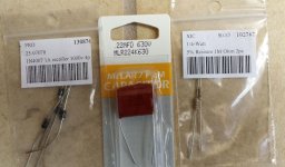
If the ignition coil is breaking down, they just don't make that one any more and, again, I wish I had pursued some ideas I have had in the past about "experimenting" with currently available components as replacements. Then I could tell you.... "yeah, go ahead and buy a 1994 BF 8 coil and slap it on"....but I can't. I know how frustrating this probably is for you...it is for me I know.

I have a VERY full plate right now for chores but I will not forget about you and will keep trying to find you some answers from the junk I have laying about my place.
 
I would like to do the voltage test; if nothing else it will be a learning experience. Can you help by explaining how to do it?

I would assume that I should disconnect the grey coil from the circuit and connect the red lead of the tester to it's one connection.....and the black lead to ground?

Any idea what range the meter should be set to? AC Volts? Do I need a peak voltage adapter on the tester?
 
Last edited:
You do have a knack for this stuff.
You are correct on both points.
Make your connections just as you describe and set the meter to ac volts.
If you're meter has a min-max feature, use that to capture peak volts reading as you crank the engine.
Let us know what you find.
 
I've been hittin' the books on this and it is looking more and more like the ignition (black) coil is the culprit. I can't find any reference to ANY magneto coil that has a primary resistance of over 2 ohms such as yours has. I've read a couple of troubleshooting guides that specifically list 1 ohm primary resistance as "good". This, along with my findings of 1.5 on some of the old coils leads me to believe that the ones I've measured at 1.5 were probably still "doin it" but were FAR from being "as new". And, the later model used coils I've measured at 1ohm and below would seem to buttress that theory.

I know I probably asked already but are the plugs new? If not I, wonder if you would have any luck trying new ones? It might just give that old coil an optimum path to fire through. Other thoughts are...have you scraped the metal inside the spark wire "boots" to clean and shiny?

And, while carb cleaner SHOULD work as a testing fuel, I would REALLY like to see you try some propane if at all possible to see if she will at least cough. Propane is so good for this because it easily reaches "stoichiometric" (14.7:1)
air/fuel ratio with the atmosphere as it comes out of the bottle because it is already vaporized. If you have one of those little home plumber propane torches and can get a helper to pull the engine over while you shoot the gas into the carb intake, if there is ANY possibility of getting it to run, this would do it. What's the point you ask? Well if she "talked" to you a bit, it would really be encouraging for one thing and it would also eliminate ANY possibility that it could still be a fuel issue.

Ok, so, if it's the coil, what are we going to do about it? Stay tuned...I'm still trying to figure that out. I've got some Ideas.

Are you going to try and check the primary (grey, under the flywheel) coil output? I can't find specs for that either but I see references for up to 300 volts ac! I think it's reasonable to expect to see AT LEAST 25 to 50 volts cranking from that coil.

Don't give up yet!
 
I can see a bit of a problem with the way you are testing......

Unfortunately the output of these types of coils is rather peaky:confused: 
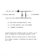
..what they do is have very sharp rise and fall times and (probably more important) relatively short duration. The meter you are using is meant for reading AC, that is continuously varying (constant level) voltage:confused:. What you really need to accurately test this type of pulse is an oscilloscope. You don't have one but a good auto electrician might have.

If you had a peak hold meter you might get a reasonable reading as successive pulses add to the reading, but there are no real guarantees. Your readings MAY be right but they might be wrong once the coil has a load on it. They may be wrong but still give some seemingly valid reading :( The trouble is you still will not be sure you have either the correct or incorrect reading reading or whether its your method of reading....:(

Its like Donald said.....there are the known knowns, known unknowns & there are the unknown unknowns....

But its not all doom and gloom.

I like the propane test. Generally if you have any spark at all it should ignite the propane (or something like CRC aerostart or equivalent).
It may be hard to see but what is the cam that operates the points like? Is it worn? If its worn it may have altered the timing enough that the points are closing earlier than they should when the voltage produced by the primary coil is not at its optimal...if you get even one cough, then the ignition is working somewhat...

I think the circuit uses the magnet/pickup coil to store a charge in the capacitor, then the points discharge the capacitor through the ignition coil. (CDI - Capacitor Discharge Ignition)

With the Ignition coil disconnected, after cranking the engine a bit try to measure what the charge on the capacitor is. It should hold the charge for a little while without the coil attached. It should be in the order of 100~400 Volts but again its one of those known unknowns, the designers may have designed it to work with a particular ignition coil and a lower voltage.

I have seen these types of ignition systems on bikes & stationary engines (Briggs & Stratton? ) and the spark duration is usually very short so they look feeble (sort of brownish and very thin) to the eye but they work OK. When the coils fail they generally fail completely, rather than the spark becoming feeble. One thing that does fail is they break down the insulation to ground. Try turning the engine over in the pitch black dark with a spark plug on a lead (and grounded) and you will see any external leakage. Unfortunately, if its breaking down to ground internally you wont see it, but usually this will show up as a resistance to ground.
 
One other thing. Did you short the meter leads together (on the 200 ohm range) This will tell you what the resistance of the leads themselves are and this has to be subtracted from your readings.

Example if the shorted leads measure 0.4 ohms, then if you measure the coil as 2.1 ohms the real reading for the coil is 2.1 - 0.4 = 1.7 ohms. These types of meters are generally not ideal for measuring resistance values below about 5 ohms unless the lead resistance is taken into account. When you are measuring in the kilo ohms the lead resistance can be ignored.
 
OK I just looked back on the circuit and its NOT a CDI system :eek:, it seems to be a simple magneto but it may have a little variation. (some designers have strange ideas about not fixing things that aren't broken and change things because they can....). Since it produces some spark at all, it is working and I think the coils should be OK.

The only other thing that can be wrong is the adjustment of the points. In magnetos, the point adjustment is somewhat critical in that the points need to open (or close depending on the circuit design) in just the right place relative to where the magnets are sweeping past the coil. A maladjusted point WILL produce a weak spark. It is somewhat "normal" for the points to arc a little.

Do you have any information at all on adjusting the points? It may be a matter of "bending" the stationary side of the points rather than any screw. You need the specification or a factory manual on adjusting the points.
If the part of the points that rubs on the cam (that causes them to move) is worn you my NOT be able to adjust the points satisfactorily, as that sets the time in relation to the magnet/coil. If the insulting part of the points that rubs on the cam is dry (no grease) then it will be worn. Is there any evidence of insulation "dust" on the cam which would indicate a worn point block?

Generally for this laymen, this is a black art and you might want to try and find someone who knows about these circuits. Maybe try a good experienced (old?) lawnmower mechanic, or stationary motor mechanic who may be able to point you at someone who knows a general procedure, if you can't find a factory manual. Even a chainsaw mechanic may know a general procedure.

If all else fails, measure and record the point gap as it is now and try to close up the gap a little. If no improvement then try opening just a little. If neither provide any improvement set the points back to where you first measured them. You are not really any worse off
 
Wow! someone new has come to the party! Thanks Berniek! All the way from Australia!

The points look very very good to me; I have them set at 0.014. The range for adjustment as shown in the Honda Service Manual is 0.012-0.016....so I picked the middle. I "dressed" them properly. The cam that operates them seems fine as well.

I imagine that it I had the genuine Honda ignition checking gadgets...the failing component(s) would be obvious after testing. I know that the simple sort of meter I have cannot replicate the loads and what-not.

I will try and take a voltage reading off the grey primary coil; although the meter I have does not have a peak reading adapter; I can make one eventually. There is not much to them....basically just a capacitor and a resistor....I have a schematic with which to construct a simple one.

I have not tried new spark plugs. I could try propane.....I spin the motor over with a drill....so I could probably do the propane test by myself.

But; I am used to the magneto ignition used on OMC engines....the spark produced by those is just SOOOOO much stronger and brighter than what I am getting here. I really think that anything short of identifying and replacing the failed part (if it was available!) is not going to help much.

I'm in this for the learning experience as much as anything though....so the tests will continue :)

Berniek...it is **VERY** interesting that you mention the resistance of the tester's leads. I noticed that with my cheap tester....and I thought it was a defect in the tester. When I touch the leads together; I expected to get "0" ZERO. Instead I get 00.6 on the 200 ohm scale....if I wait a few seconds. So; I guess my readings need to be lowered by that amount? Thanks for mentioning that.

The voltage test (without a peak adapter) will happen later today; weather and my schedule permitting. Thanks so much again jgmo racerone and Berniek!
 
Well....with the basic meter shown in the original test images....without a DVA adapter....I get 3.2 volts. I guess that's essentially meaningless. I need the DVA adapter to do the test.
 
racerone; I'm not sure what you mean. I certainly have some OMC coils kicking around but I don't know how I would use them in the Honda. Can you elaborate?
 
Oh; OK Racerone....I was mistakingly thinking that the 1976 still used the two coils under the flywheel....the version OMC used since the 1950's....

I looked up the coil you are talking about; it appears to have two leads coming from it (in addition to the SP lead) but I suppose one of them is just ground or kill-switch wiring etc. I could give it a try.

I am also ready to assemble my DVA adapter. I have a schematic that's been kicking around the forums for years...and today I bought the parts; Four dollars and change for the stuff shown in the picture.

Thanks guys....
 
What picture? Did you load photos? I can't see them.
As far as zeroing out the meter, my mistake for not clarifying that. Even the old analog "sweep" meters have a provision for that and I just assumed everyone does it.

Berniek raises some interesting points, not the least of which is...wait for it...POINTS! Oh my!
His comments about the cam being worn is pertinent. Although, the point assembly itself is designed to "ablate" or wear down to prevent this from happening.

But, his comments about timing of the opening of the points leads to what is known "dwell ". Dwell refers to the amount of time the points are in position to allow the coil to "charge up" before being "tripped" and causing a "firing event". Dwell is built in to the system for the most part so that if the points are new and properly adjusted, it should just naturally occur. But, if there's wear to actuation cam or to the point "arm" that rides the cam, dwell could be affected. A"weak" set of points with poor spring "action" will also shorten dwell as well as cause the points to "bounce", keeping the coil from fully charging. They used to actually sell "dwell meters" for checking this but I haven't seen one in years. Although I probably have one in my barn!

Ok...hree comes the next sad pun.....give it a sec.....

This would be something to DWELL on!......OH MY!
 
Sorry about the pictures. I uploaded them. I'll try again.

I remember DWELL meters; I might very well have an old SEARS DWELL meter kicking around here someplace. Never really knew what the thing did; once I set the point gap...the DWELL always checked good lol.....

Should get my DVA adapter done today; looking forward to having that available to me; I have lots of stuff to experiment with using that on; it is an essential component for ignition testing to be sure.

One of the issues I have with this motor is that I have no history for it. It came to me after a long life .... The rewind spring broke on it at some point and it was put away. That was most likely many many years ago. The PO said that prior to that "it ran great"....
 

Attachments

  • DVA_Parts.jpg
    DVA_Parts.jpg
    50.3 KB · Views: 155
  • DVA_adapter_schematic.jpg
    DVA_adapter_schematic.jpg
    32.4 KB · Views: 221
Well, that last bit O history is what I would normally say indicates that the problem is fuel delivery. "Ran great when put away" typically points to carb deposits and not electrical coils breaking down while not in use....???
I would still like to see what happens with a propane attempt.

Not sure about the DVA helping you with checking the grey coil. You should be able to read the alternating current that coil produces directly with your existing meter...and I believe that you already have...3.2v.

But...

Were you on the AC volt scale? If so, that seems way low and I don't know how you would be able to drive an ignition coil to get even a weak spark. But, I am still learning here too so maybe I'm wrong and that DVA will get some better results. At any rate, thanks for the schematic...I'm gonna make me one too!

One last thought is: Are you sure that your "using a drill to turn over motor" is producing enough RPM for this puppy to catch? Have you tried it by hand, with an emergency rope? The coil is rpm sensitive and a weak spin...by hand or by drill...will have the voltage it produces low. My answer to your question about what the OMC coil wants is a MINIMUM of 6 volts...

WHAT DOES RACERONE SAY??

ANYONE ELSE???

At least you're willing to keep diggin' and asking/answering questions.

I LIKE THAT!
 
Well; wired up the DVA and not really sure what to make of the results. Pretty much the same as before.

The drill spins it over at a pretty good clip; especially with the spark plugs out.
 
I've been a voyeur on this quest. I am currently working on a B100 with points but different coils etc. and no technical specs on voltage, but I might be able to add something here.

So here it is...just what you need....another opinion.

One other check for you capacitor is to see if there if you can measure any resistance across the terminals. You want to make sure that there is not an internal short. Before you measure for resistance, take a jumper and short it across the capacitor leads....otherwise, if there is a charge on it, it will discharge through your meter and could harm it.
If the motor was sitting, the capacitor could have leaked and possibly developed an internal short. You can take the measurement with the capacitor still on the engine. You just have to disconnect the lead going from the points to the spark coil and make sure that the points are open.

Try taking your voltage measurements with your DVA circuit with your meter set to read DC not AC. I suggest the DC setting, since the diode allows only the positive waveform of the AC charge the capacitor. Since the capacitor is being charged, its charged state is best measured with a DC Setting.

A simple way to make sure the points are set correctly.....disconnect the wire that goes from the points to the spark coil from the spark coil. Set your meter to the ohms setting but choose the mode that will give you an audible signal when the leads are shorted together. It does look like your meter has that setting.
Now, connect one lead to ground and the other lead to the wire coming from the points.
As you turn the flywheel clockwise by hand, watch the "F" mark on the flywheel. As the "F" mark comes to the timing mark on the powerhead, the tone should go away....indicating that the points are just opened. If it does not, adjust the points until it does. If you continue turning the flywheel, the tone will come back...until the "F" mark reaches the timing mark.
Theoretically, if you are setting the points to the points gap it should be very close to the tone only method. I have always adjusted to the tone and it has always worked. If you need to fine tune (advance or retard timing) a little for a good idle, you just have to change the point setting by a hair.

All that being said, by the time I read through all the posts I forget what was said in the beginning. Jimmy's last post indicated that this motor ran ok when it was put away. I know you said that it would not hit on ether, carb spray or whatever, but it still could very well be the carburetor. You said that you had spark, but it was very small. So I am thinking down the same path as Jimmy...that it could be the carburetor.

It is not unusual for some of these motors not to hit on anything sprayed into the carburetor but it turns out to be the carburetor.

It appears from your pictures, that you have either a BF75K1 K2 or K3 model. If that is the case, I do have one at the shop that we use for display. We had it running a few years ago. I will see what I can do about checking what the voltage going into the spark coil should be....I think it will be around 125 - 150 v but that is only a guess at this time. I will report back, if I can get to it....it might be a couple of days, since we are slammed at work, now that the sun is starting to come out again.

Mike
 
Sorry to rain on the parade

I think you are back to the "known unknown" stage.

Technically the circuit you have built has a discharge Time Constant (TC) 220 milliseconds (milliseconds is 1/1000 of a second)...The capacitor discharges by 67% of its charge each TC..... a close enough rule of thumb generally accepted that it takes 5 TC to discharge a capacitor.
(If you started at 100V then 1 TC you would have 33Volts, after another TC you would have 10 Volts, after the third there would be 3.6Volts.....and do on)
Note I said discharge; discharge is when you are reading the voltage from your boat coil. So immediately you start reading it with your meter after half a second you will read have less than 10% of the voltage.

So what about charging, well the TC for charging is REALLY hard to figure out because the resistance is very low but it also has a coil which has a different type of resistance called impedance (it depends on the inductance of the coil) BUT the voltage isn't constant once the points open. As soon as the points open current stops flowing in the coil and the magnetic flux produced by that current collapses really, really, really fast and induces the voltage pulse (called a back emf ) that will be fed to the ignition coil. The time pulse is really really short. (in the order of microseconds - microsecond = 1/1000000)

So what the very voltage you are trying to charge up your little measuring circuit with is very short, probably shorter than even 1 TC of the charge TC of your circuit. It means its going to take a high number of these pulses to charge up your little circuit.

If you are rotating the engine at idle speed 600rpm then you get a pulse every 100milliseonds, but you are starting so a good speed for starting is probably 200rpm so the pulse will be 300millseonds apart
Now while your circuit is charging its also discharging.... and it discharges more than 67% of the pulse even before it gets the next pulse.
I realize this is a lot further into theory than anyone needs to know for this forum but if anyone wants to hit the net this will give some understanding of where to start.

Well back to test the coil. It may work if you can keep the motor turning sufficiently long enough to charge up your capacitor. It would be better to remove the 1 meg ohm resistor completely. Your meter will have an input resistance of around that value anyway....and on the meter, the update rate will be in the order of a couple of times a second (how often it samples the input and puts it up on the digital display), so even between the updates the capacitor discharges a bit.....
Whatever you connect to a circuit loads it to some extent. Just a meter may add 1~10 meg ohms (meg = X1000000). A capacitor looks like a short circuit instantaneously when discharges, but looks like an open circuit when fully charged, an inductor looks like a n open circuit till the current is fully flowing and the resultant magnetic flux is steady in it and then it looks like a short circuit (that's why they have impedance rather than resistance)

so the known unknowns are:

1 the impedance of the primary coil
2 duration of the pulse, the design engineer determined this
3 effect of the diode capacitor has on the coils characteristics. It may load it to the point where it simply doesn't work or it may work in some way the designer never intended, so the results are meaningless anyway.

Unknown unknowns are whether the results are meaningful.

By all means try.

Basically what the primary should produce is a pulse of at least 80 volts (but more likely 150 or more) but it is very short duration so very hard to measure.

Just a thought out of left field

You could try connecting your neon testor directly to the primary coil. Neons should flash at about 50~70 volts (note I said should, I don't know your testers details).
You may need to be in the dark to see it since it will be really fast. If it does flash connected to the primary (without the ignition coil in place) then you can be almost certain this part of the circuit is working correctly and the ignition coil should produce a good enough spark.

Even if it doesn't work you are still no worse off.

If it does, connect it to a car coil with the other terminal grounded and it should produce a good fat spark on a spark plug (also grounded) and you will be certain the primary, points & magnets are working.
 
Well Well Well....lots of material to digest. Thanks so much for all the interest in my tired and long neglected (abandoned) little Honda.

Hondadude! Great to have your input. It was the link to the Honda Model/Serial/Year chart over at hondapartsus.com that you so helpfully posted a while back that allowed me to ID my engine. According to that chart...mine is a B75 K2 (1975).

For others:
http://www.hondapartsus.com/forum4/

Hondadude...I did do a basic resistance test on the capacitor when it was out of the engine. It does not appear to be shorted. I will try testing the Primary coil with the meter set to DC today and see what happens. I understand your method of setting the points with the meter; I can try that as well. I think my point setting is likely to be pretty close.
Yes; my motor was said to have run great when last used.....but everyone says that about an old engine hahaha....it was last used **many** years ago.....
I dunno....everyone is saying that the primary coil should produce 80-150 volts...and; if mine is truly putting out 3.2....well.....that doesn't seem to leave much doubt as to what is wrong. Yet; it **does** manage to produce a weak spark.

Berniek.....thanks for the theory. I understand some (very little) of it...but I imagine it will make more sense the more I think about it.
I understand about the voltage dropping within the DVA circuit. I know that the purpose for the resistor is to do that very thing: drain down the voltage so no one gets zapped when the test is done. I think I will dis-connect the resistor and see if anything changes. The resistor **is** optional in the circuit. Others who have used it have done without the resistor.
I will try hooking the neon tester directly to the Primary coil. Easy enough. I'll let you know. The idea of substituting a car coil....or a Johnson coil as racerone suggested) is also something that's worth a try. I just need to find something suitable.
 
I was hoping you would do the foot work with 2 of the 1975 25 HP Johnson coils.---Would save me the time on the 3 older Honda motors that I have ( same as yours ) with one having known weak spark.
 
Berniek has an interesting point. He flashed me back to Electronic Circuits 101. When I first saw the circuit diagram, I was thinking to myself that the capacitor seems to be too small and it was not an electrolytic capacitor with a positive and negative, then got lost in the other info. So I just googled up the same circuit but the capacitor value there was 2.2 ufd. That should increase the discharge time by at least a factor of 10.

So you may want to double check the component values from other sources.
172212d1304903560-how-test-1999-yamaha-s150txrx-stator-dvacircuit.jpg


Mike
 
Last edited:
Interesting Hondadude....I will certainly check components from one suggested circuit to another. I thought about the capacitor not having polarity; thought it was odd but I don't know enough about it to really tell me anything.

Here are today's tests:

ON DC-Volts....without the DVA attached: no reading or erratic flashes of - (negative) on the meter
WITH the DVA with resistor in the circuit 10 volts DC (appx)
WITH the DVA with the resistor removed 12.8 volts DC.

Still.....far far far below what most of you feel it should be.

I also tested the points with the ohm-meter.....and the beeping stops just a bit past "F"; actually about half-way between the "F" and "T" markings on the flywheel. Perhaps the points should be adjusted by a tiny amount to "fix" that....but is there any reason to think that it's causing the primary issue of weak spark?
 
Oh; one more thing I forgot to add.

I did hook up the neon tester directly to the grey primary coil as Berniek suggested.....and NOTHING. Even in a completely dark garage.....no trace of any glow.
 
I do not think that the small difference in points setting is causing your problem.

I still owe you some voltage readings. Will try to do that tomorrow. We have a B75K1 here that has the same coils etc.


Mike
 
Chicken & egg thing with increasing the time constant by having a bigger capacitor.

It will increase the "retention" time BUT it will also increase the time it takes to charge up, especially if the charge pulse is very short.

One way thing to try is connect the circuit without the resistor & without the meter. Turn the engine for a minute or so and then attach the meter. You may need to take the meter off auto ranging if possible and set it to the 200V range or whatever range is close. This is because the auto range feature takes time to operate and as soon as the meter is connected the capacitor will start discharging.

Well, the neon was worth a try but not seeing it doesn't really mean all that much. We know it produces something but maybe not enough for that particular neon.

One other thing that might be worth a try is to reverse the diode in your circuit. As far as producing a spark goes, it doesn't matter whether the pulse is positive or negative so the 100V or so may actually be -100V.
In theory at least the primary circuit should produce both positive & negative pulses, one being much bigger than the other and the ignition coil doesn't really care whether it gets a positive or negative pulse.

One thing I cant see from any of the diagrams is whether adjusting the timing is independent of where the points are compared to the magnets. Generally for a good spark the points opening with respect to the magnet/primary position is more important for the size of the spark than whether its at the right place for the cylinder. The way its described in the manual suggests that the magnet position is fixed and fine adjustment to timing is done by altering the point opening.

It might be worth fixing the timing as per the manual, it can't hurt.

In a good design it would be prudent to adjust the points to get optimum spark then adjust the points/magnet/coil as a group to get the timing, but we are talking old design and reliability and that usually means the KISS principle (Keep It Simple Stupid)
 
Ignition Timing: Other than the points...there is no way to adjust static timing (the base timing at cranking speed). The stator plate on this engine is fixed, so no timing advance occurs when the throttle is opened; as in many outboards. The position of the coil and magnets is not adjustable in any way. But; as the engine revs...there are weights and springs that change the adjustment of the point-cam....Honda's way of achieving timing advance...in relation to RPM as opposed to throttle setting.

When hondadude gives me voltage readings off of his engine....I hope he shares his method of taking them ...and I hope that method is something I can re-produce with the instruments I have. At least then I will have something to compare...apples to apples.

I can see why people find themselves tempted to throw parts (and $$$) at these sorts of problems. Good thing we all work cheap; eh? The "billable hours" are climbing LOL!
 
It's cheap, but this one ain't been easy!

I found out that my Fluke 87 V meter has the speed needed to capture the pulse rates of these coils. It is a relatively expensive meter but is still at the "bottom of the list" of meters that can accomplish this. So, I apologize for trying to get you to use your meter that I now know can't do it. Berniek's info explains why but I have to admit much of it is over me head.

I have also come across a good deal of reference about CDI flywheel "stator" voltage in the 200 to 300vac range. I can't find anything referencing breaker point ignition values but, unless Mike's tests prove otherwise, I would think that the necessary volts to charge the ignition coil must be pretty much the same for both types.

Hopefully, tomorrow we will all know. That is unless a burning boat rolls through hondadude's shop doors!

Waiting....watching....zzzzzzz.
 
Back
Top