If the TRAILER button raises the engine then the problem is in the shifter handle; either the TNT switch or a wire is disconnected. There is a flat plastic wire harness connector in the handle assy. Look there.
How the trim/tilt works
Before you tear anything apart or replace wiring and switches, test it out; firstby visual inspection by pulling back and forth on the wires while operating theswitches and then test with a meter. At the commander switches ,the red wirewill always have 12 volts. The green wire gets 12 volts when the trim toggle isheld down. The blue wire gets 12 volts only when the toggle is held up or thetrailer switch is pushed in. The purple wire is part of the limit switchcircuit.
If the switch voltages are as they are supposed to be then go to the trim/tiltpump assy. and make sure the purple wire connector (single wire) and the bluewire connector with two blue wires on one side of the connection are notcorroded or loose. These are the trim position and limit switch wires. Pullthem apart and inspect; they should be clean and tight; reconnect them. Ifnecessary, trace the wires to the front of the engine near the slave solenoid.One wire is grounded near there and the other is connected to a terminal. Ifyou don't get a voltage reading at the terminal junction, apply 12 VDC to seeif the trim gauge moves. If it does, check for voltage back at the trim pumpconnections. If there is no voltage there, apply 12 VDC there to check gaugemovement.
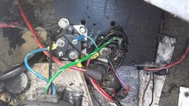
Next check the three wire connector (RED, BLUE & GREEN) at the pump assy.This plug can vibrate loose and cause your problem. Pull it off and see if the pinsare clean and not corroded; reconnect it.
The RED wire in the plug sends 12 volts from the pump assy. to the toggleup/down and trailer up switches. The BLUE & GREEN wires bring 12 volts fromthe toggle trim/tilt and trailer switches to the two solenoids on the pumpassy.
The GREEN wire goes to the DOWN solenoid while the BLUE wire goes to the UPsolenoid.
Did you check the switches with an ohmmeter? The trim/tilt switch is a 2-wayswitch and will show continuity only when it is toggled in each directionbetween two of the wires.
Up toggle connects the RED wire to the BLUE wire. Down toggle connects the REDwire to the GREEN wire. The TRAILER UP switch also connects the RED wire to theBLUE wire.
The OD trim limit switch will only send voltage to the trim/tilt switch in theupward toggle position if the OD limit switch is below the adjusted trim limitthat keeps the OD being out of the water.
To test the limit switch circuit, lower the OD to the down position and slowlyraise it with the trim toggle up until it stops. Then measure the distancebetween the trim cylinder attaching bolts. If the distance is approx. 20 +/-1/4inches, then the trim limit switch is adjusted properly and the commander trimtoggle switch is working in the up/down mode.
Go to the trim/tilt pump assy. and make sure the purple wire connector (single wire)and the blue wire connector two blue wires on one side of the connection arenot corroded or loose. Pull them apart; they should be clean and tight;reconnect them. Next check the three (RED, BLUE & GREEN) wire connector atthe pump assy.The RED wire in the plug sends 12 volts from the pump assy. tothe toggle up/down and trailer up switches. This plug can vibrate loose andcause your problem. Pull it off and see if the pins are clean and not corroded;reconnect it.
The BLUE & GREEN wires bring 12 volts from the switches to the twosolenoids on the pump assy. The GREEN wire goes to the DOWN solenoid while theBLUE wire goes to the UP solenoid.
Disconnect the trim/tilt assy. wires from the battery and then check each ofthe nuts and studs on the solenoids for clean and tight fittings. Each solenoidhas three wires and the buss bar connected to it. The bases of them have ablack ground wire and a small blue wire to one and a small green wire to theother.
On top of each solenoid, the large BLUE wire from the pump motor attaches to alarge copper stud with the solenoid that has the small blue wire at the base whilethe large GREEN wire from the pump motor attaches to a large copper stud withthe solenoid that has the small green wire at the base.
The other copper solenoid studs are connected together with a copper buss bar.One of the two studs will also have a funny looking 110 amp fuse attached tothe bar. The large RED wire from the battery connects to the 110 amp fuse. Thislarge red wire is the power for this buss bar. A small RED wire attached to thebar stud sends 12 volts to the switches which in turn sends the 12 volts to thesolenoids which turns on the pump motor.
Important: if the studs on the either solenoid are dark and not like a cleanpenny, especially the BLUE wired solenoid, this solenoid is failing due to ageand/or a loose bottom copper stud nut. The dark color comes from heat generatedinside of the solenoid by the contactor because it is arcing like weldingsimilar to points wearing out. Change the solenoid.
Cleaning Trim Limit Switch & Trim Position Sender
For the trim/tilt, if the wires from the limit switch (port side) and trimposition sender (starboard side) are in good condition, they (Switch or sender)can be disassembled to clean out the old hardened grease. SCRIBE the sides ofeach one and the OD for a reference mark before removal. Clean out the oldgrease and pump fresh Mercruiser 2-4-C grease thru the zerk fittings beforereinstallation. Clean the small brass contact points with solvent and a pencileraser until shiny; repack w/ 2-4-C grease and reinstall by aligning reference marks.